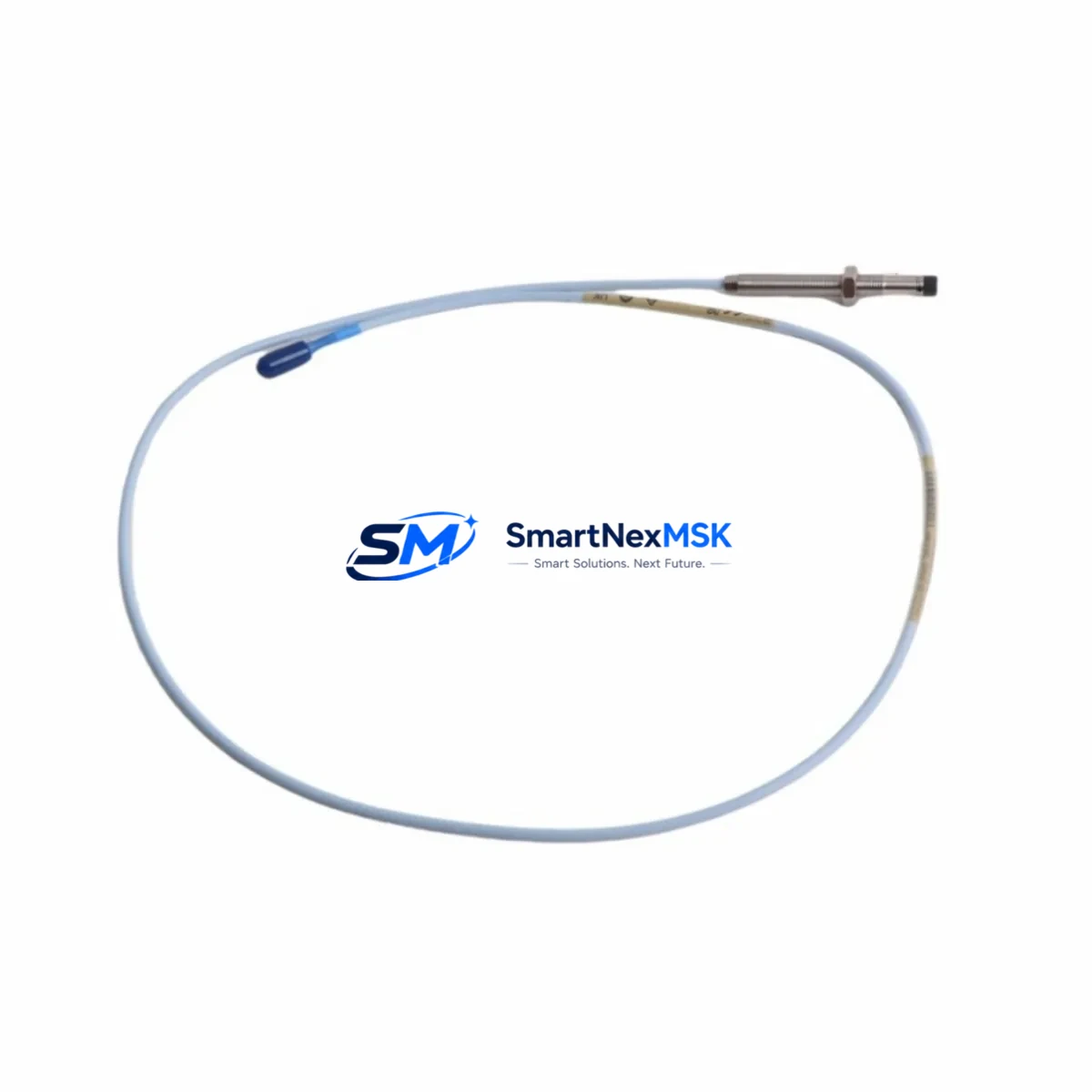
Bently Nevada 330102-00-15-10-01-05 Maintenance-Ready Spare 3300 XL
The Bently Nevada 330102-00-15-10-01-05 is an original 8mm eddy-current proximity transducer engineered for the 3300 XL continuous machinery monitoring system. In rotating machinery environments — turbines, compressors, pumps, and gearboxes — this transducer serves as the primary sensing element for shaft radial vibration, axial position, and differential expansion measurement. When this component fails or degrades, the entire protection loop is compromised, leaving critical rotating assets unprotected and exposing the facility to unplanned shutdown risk.
Sourced as an original spare, the 330102-00-15-10-01-05 is fully compatible with the 3300 XL proximitor/seismic monitor series and integrates directly with Bently Nevada’s 3500 rack-based machinery protection system. Each unit is pre-shipment tested against factory electrical specifications, including gap voltage linearity, sensitivity coefficient (7.87 V/mm nominal), and frequency response, ensuring drop-in replacement without recalibration of the monitoring channel.
For maintenance engineers managing turbomachinery protection systems, holding this transducer in the on-site spare parts inventory is a fundamental risk-mitigation strategy. A single unplanned outage caused by a failed proximity transducer can cost far more than a stocked spare. This unit ships with a 12-month warranty and full traceability documentation.
Spare Maintenance Table
| Parameter | Specification |
|---|---|
| Part Number / SKU | 330102-00-15-10-01-05 |
| Brand | Bently Nevada |
| Series | 3300 XL |
| Transducer Type | 8mm Eddy-Current Proximity Transducer |
| Sensitivity | 7.87 V/mm (200 mV/mil) nominal |
| Operating Range | 0.25 mm – 2.26 mm (10 – 89 mil) |
| Supply Voltage | -24 VDC (via proximitor) |
| Cable Length | 1.5 m (5 ft) integral cable |
| Thread | M10 x 1 (metric) |
| Temperature Range | -35°C to +121°C (-31°F to +250°F) |
| Compatibility | 3300 XL Proximitor, 3500 Series Monitor Racks |
| Application | Radial vibration, axial position, differential expansion |
| Origin | USA (Original Bently Nevada) |
| Condition | Original spare, pre-shipment tested |
| Warranty | 12 Months |
Maintenance Planning for Continuous Operation
When a maintenance or reliability engineer schedules replacement of the 330102-00-15-10-01-05 proximity transducer, the scope of work should extend beyond the transducer itself. The 3300 XL measurement chain is a system — and each element in that chain must be verified to ensure the protection loop is fully restored after the transducer swap.
Begin with the 3300 XL Proximitor/Seismic Monitor (e.g., 330180-X1-05), which conditions the transducer signal and outputs the gap voltage to the monitoring rack. If the proximitor has been in service for an extended period alongside a degraded transducer, its internal circuitry may have been stressed by out-of-range signals. Verify gap voltage output and sensitivity before returning the channel to service.
Next, inspect the extension cable assembly (typically 330130-series or 330140-series armored cables). Extension cables are frequently overlooked during transducer replacements, yet connector corrosion, jacket abrasion near bearing housings, and shield continuity failures are common root causes of intermittent vibration channel faults. Replace the extension cable if any physical damage or high-resistance readings are found.
At the rack level, confirm the 3500/42M Proximitor/Seismic Monitor module channel configuration matches the replacement transducer’s sensitivity and gap range. If the facility uses a 3500/20 Rack Interface Module (RIM) for system communications, verify that the channel is correctly mapped and that no latched alerts remain after the transducer replacement.
For installations where the transducer feeds into a 3500/22M Transient Data Interface, ensure the transient recording configuration is re-enabled after maintenance. Facilities running older 3300/16 or 3300/20 monitor cards in legacy racks should also verify that the replacement transducer’s output is within the monitor’s input range, as mixed-generation hardware can introduce compatibility edge cases.
On the power supply side, check the 3500/15 Power Supply module output rails. A marginal power supply delivering slightly low -24 VDC will cause the proximitor to operate outside its linear range, producing false vibration readings even with a new transducer installed. This is a frequently missed step during field replacements.
Finally, if the machine is equipped with a Keyphasor transducer (e.g., 330980-series), verify its gap and signal quality during the same maintenance window. Keyphasor signals are used for phase reference in all synchronous vibration measurements — a degraded Keyphasor will corrupt vector data across all channels on the machine train, making post-maintenance vibration analysis unreliable.
Site Replacement Workflow
Step 1 — Isolation and Lockout: Follow site LOTO procedures. Inhibit the 3500 rack channel to prevent spurious trips during transducer removal. Document the existing gap voltage reading before disconnecting the transducer.
Step 2 — Transducer Removal: Disconnect the extension cable at the transducer connector. Unthread the 330102-00-15-10-01-05 from the mounting bracket using the appropriate spanner. Note the installed gap (thread depth) for reference during reinstallation.
Step 3 — Replacement Installation: Thread the new 330102-00-15-10-01-05 into the bracket. Set the initial gap to the midpoint of the linear range (approximately 1.0–1.27 mm / 40–50 mil). Reconnect the extension cable and verify connector seating.
Step 4 — Gap Voltage Verification: With the machine stationary, measure the gap voltage at the proximitor output. The reading should fall within the linear range specified for the 3300 XL system (typically -10 VDC ± 2 VDC at nominal gap). Adjust thread depth as needed to achieve the target gap voltage.
Step 5 — Channel Restore and Functional Test: Remove the channel inhibit in the 3500 rack. Verify that the monitor displays a valid vibration reading with no alert or danger conditions. Confirm OK relay status. Document the final gap voltage and thread depth in the maintenance record.
Step 6 — Return to Service: Notify operations that the protection channel is restored. Update the CMMS with the replacement date, new part serial number, and gap voltage as-found/as-left data. Place the removed transducer in the failed-parts quarantine area for root cause analysis.
Spare Parts Support FAQ
Q1: Is the 330102-00-15-10-01-05 a direct drop-in replacement for older 330102-series transducers?
Yes. The 330102-00-15-10-01-05 is backward-compatible with earlier 330102-series variants used in 3300 XL and legacy 3300 systems, provided the extension cable and proximitor are also 3300 XL-compatible. Always verify the complete measurement chain — transducer, extension cable, and proximitor — for system-level compatibility before installation.
Q2: What pre-shipment testing is performed on each unit?
Each 330102-00-15-10-01-05 unit undergoes electrical verification including gap voltage linearity check across the full operating range, sensitivity coefficient measurement, and insulation resistance test. Units that do not meet factory specifications are quarantined and not shipped. A test report is available upon request.
Q3: What is the recommended spare parts stocking strategy for this transducer?
For facilities with four or more machines monitored by 3300 XL or 3500 systems, a minimum of two 330102-00-15-10-01-05 transducers per machine train is recommended as on-site inventory. Given the transducer’s role in the protection loop, a stockout during an unplanned outage is a high-consequence event. Long-lead procurement risk is also a factor for original Bently Nevada parts — maintaining a buffer stock eliminates this risk entirely.
Q4: What does the 12-month warranty cover?
The 12-month warranty covers manufacturing defects and electrical performance failures under normal operating conditions. It does not cover damage resulting from incorrect installation, mechanical impact, or operation outside the specified temperature and voltage range. Warranty claims are processed with return of the defective unit and provision of installation documentation.
© 2026 SMARTNEXMSK. All rights reserved.
Original Source: https://smartnexmsk.com
Contact: sales@smartnexmsk.com | +86 18259474341


