Bently Nevada 330102-00-68-05-02-05 Spare for 3300 XL Automation: Precision Spare Parts for Downtime-Critical Vibration Monitoring
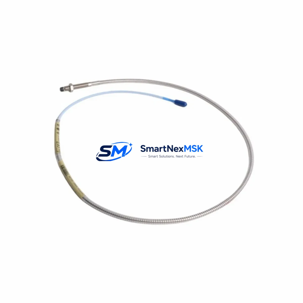
The Bently Nevada 330102-00-68-05-02-05 is an original 8mm proximity transducer engineered for the 3300 XL series vibration monitoring system. Designed for continuous shaft displacement and radial vibration measurement in rotating machinery, this transducer is a critical spare component in turbine protection panels, compressor control cabinets, and pump monitoring systems across oil & gas, power generation, and heavy industrial facilities. Maintaining a verified stock of this part directly reduces unplanned downtime risk and supports rapid fault isolation during emergency shutdowns.
For maintenance engineers managing aging 3300 XL installations, the 330102-00-68-05-02-05 represents a direct, pin-compatible replacement for worn or damaged transducers without requiring recalibration of the full monitoring loop. Its 200 mV/mil output sensitivity and -24 VDC bias voltage are fully compatible with the 3300 XL proximitor/seismic monitor modules, ensuring seamless integration into existing wiring and signal conditioning chains. Procurement engineers sourcing this part for MRO inventory can rely on our 12-month warranty and pre-shipment functional testing to meet site acceptance requirements.
Spare Maintenance Table
| Parameter | Specification |
|---|---|
| Part Number | 330102-00-68-05-02-05 |
| Brand | Bently Nevada |
| Series | 3300 XL |
| Type | 8mm Proximity Transducer |
| Output Sensitivity | 200 mV/mil (7.87 V/mm) |
| Bias Voltage | -10.0 VDC nominal (at 1.0 mm gap) |
| Supply Voltage | -24 VDC |
| Cable Length | 5m (standard extension cable) |
| Thread Size | M8 x 1.0 |
| Connector | 5-pin MIL-C-5015 style |
| Operating Temperature | -35°C to +121°C |
| IP Rating | IP67 (sealed housing) |
| Compatible Monitor | 3300 XL Proximitor/Seismic Monitor |
| Application | Radial vibration, shaft displacement, rotating machinery |
| Origin | USA |
| Warranty | 12 Months |
| Condition | Original, tested before shipment |
Maintenance Planning for Continuous Operation
When replacing the 330102-00-68-05-02-05 proximity transducer during a planned outage or emergency callout, a thorough inspection of the surrounding measurement chain is essential to prevent repeat failures and ensure signal integrity. Maintenance engineers should simultaneously verify the condition of the 3300 XL Proximitor/Seismic Monitor module (typically mounted in the same rack slot), as a degraded proximitor can mask transducer faults or introduce false alarms even after a transducer swap.
The 330130-080-00-00 extension cable connecting the transducer to the proximitor is a common wear item in high-vibration environments — inspect for chafing, connector corrosion, and continuity before reinstalling. The 3300/16 power supply module feeding the monitoring rack should be load-tested; an unstable -24 VDC rail will cause erratic gap voltage readings that mimic transducer failure. If the cabinet houses a 3500 series rack alongside the 3300 XL system, cross-check the 3500/42M proximitor monitor card for any shared signal conditioning paths.
For facilities running GE or Woodward turbine governors, the proximity signal often feeds directly into the Woodward MicroNet TMR controller or a GE Mark VIe I/O module — confirm that the analog input channel is reading within the expected -10 VDC to -18 VDC window after transducer replacement. Where signal isolation is required between the monitoring system and the DCS historian, inspect the MTL5541 or P+F KFD2-STV4 signal isolator for drift or output clamp faults. Terminal blocks in the junction box — particularly Phoenix Contact MKDS or Weidmüller WDU series — should be torque-checked and inspected for oxidation, as loose connections are a leading cause of intermittent vibration alarms. Finally, verify that the 3300 XL system keyphasor module (if installed) is providing a clean once-per-revolution reference pulse, as a degraded keyphasor signal will corrupt phase angle data across all transducer channels in the rack.
Site Replacement Workflow
Step 1 — Isolation & Permit: Obtain a hot-work or confined-space permit as applicable. Isolate the monitoring channel at the 3300 XL rack using the channel inhibit function to suppress spurious trips during transducer removal.
Step 2 — Gap Measurement: Before removing the old transducer, record the installed gap voltage (target: -10.0 VDC ±0.5 VDC at 1.0 mm). This baseline confirms whether the fault is in the transducer, extension cable, or proximitor.
Step 3 — Transducer Removal: Unscrew the 330102-00-68-05-02-05 using the M8 thread. Inspect the probe tip for impact damage or contamination. Clean the target area on the shaft with a lint-free cloth.
Step 4 — Installation: Thread the replacement transducer to the correct gap per the 3300 XL installation manual (typically 1.0 mm for 8mm probes). Reconnect the 330130 extension cable and verify connector seating.
Step 5 — Verification: Re-energize the channel and confirm gap voltage is within specification. Check the 3300 XL monitor front panel for OK status. Log the replacement in the CMMS with the new serial number and installation date.
Step 6 — Return to Service: Remove the channel inhibit, confirm no active alarms, and update the spare parts inventory record. This workflow typically achieves full channel restoration in under 45 minutes, minimizing production impact.
Spare Parts Support FAQ
Q1: Is the 330102-00-68-05-02-05 a direct replacement for older 330102 series transducers?
Yes. The 330102-00-68-05-02-05 is backward-compatible with earlier 330102 variants within the 3300 XL system, provided the extension cable and proximitor model are matched. Always verify the cable length suffix and connector type against your existing installation drawing before ordering.
Q2: What pre-shipment testing is performed on this spare?
Each unit undergoes functional gap voltage verification and output linearity testing prior to dispatch. A test report is available upon request. Units are shipped in anti-static packaging with protective end caps to prevent probe tip damage in transit.
Q3: How should this transducer be stored in a spare parts inventory?
Store in a dry, temperature-controlled environment (10°C–35°C) away from strong magnetic fields. Keep in original packaging until installation. Recommended maximum shelf storage is 5 years; inspect the cable jacket and connector pins for degradation before use if stored beyond 2 years.
Q4: What is covered under the 12-month warranty?
The 12-month warranty covers manufacturing defects, output sensitivity deviation beyond ±5%, and connector failure under normal operating conditions. It does not cover physical impact damage, incorrect installation gap, or use outside the specified operating temperature range. Warranty claims are processed within 5 business days with a replacement unit dispatched upon confirmation.
© 2026 SMARTNEXMSK. All rights reserved.
Original Source: https://smartnexmsk.com
Contact: sales@smartnexmsk.com | +86 18259474341


