Bently Nevada 330102-00-80-10-11-00: Retrofit-Ready Proximity Probe for 3300 XL Control Systems
The Bently Nevada 330102-00-80-10-11-00 is an 8mm eddy-current proximity probe engineered for seamless integration into Bently Nevada 3300 XL Series vibration monitoring systems. As legacy rotating machinery protection platforms age and original components reach end-of-life, this probe serves as a verified drop-in replacement that preserves signal integrity, wiring compatibility, and system calibration — enabling plant engineers to modernize aging control infrastructure without full system overhaul.
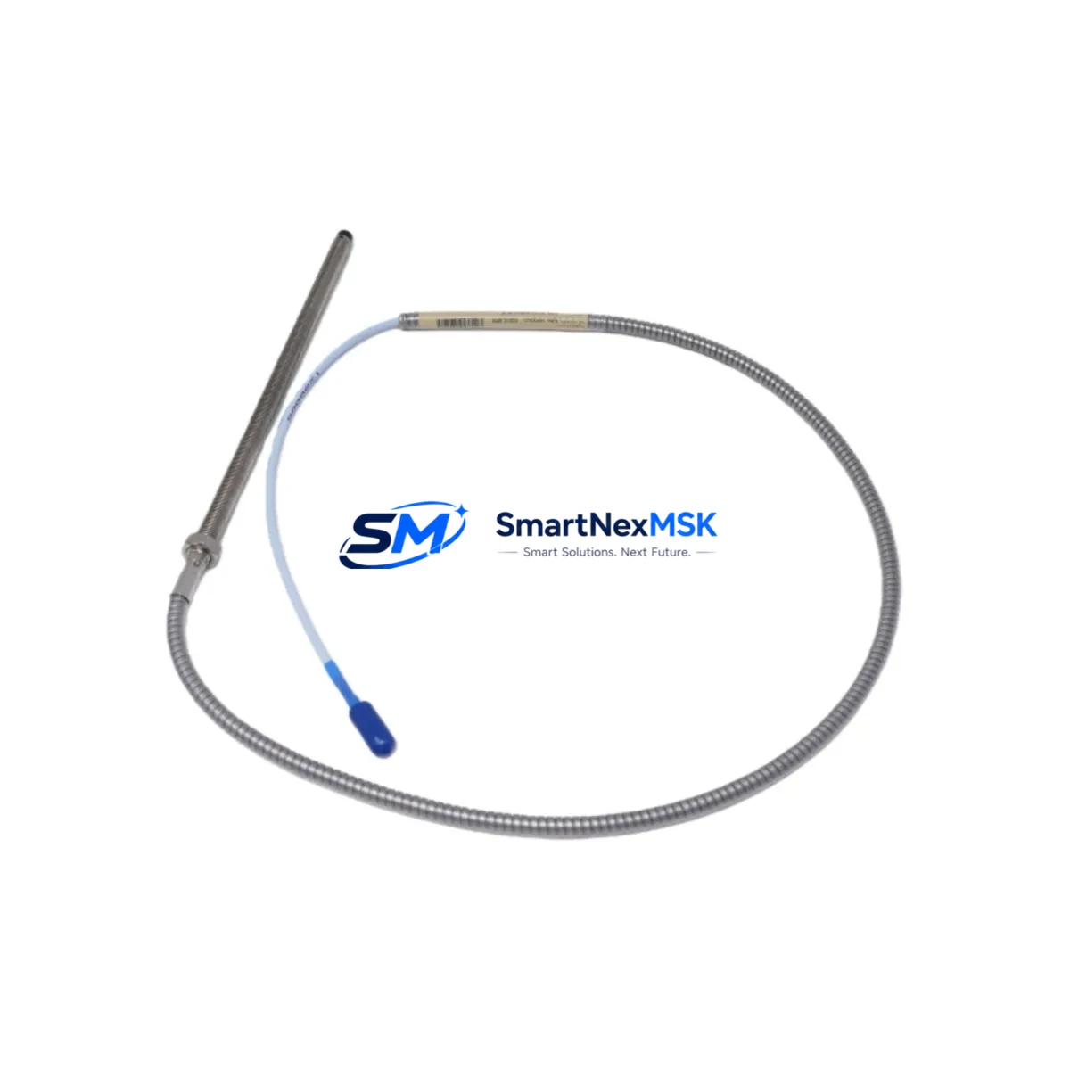
Designed for continuous shaft vibration, axial position, and differential expansion measurement, the 330102-00-80-10-11-00 delivers the same sensitivity factor (200 mV/mil, 7.87 V/mm) and linear range as the original Bently Nevada specification. Its armored cable construction and stainless-steel housing make it suitable for high-temperature, high-vibration environments common in turbines, compressors, pumps, and gearboxes across oil & gas, power generation, and petrochemical facilities.
Upgrade Compatibility Table
| Parameter | 330102-00-80-10-11-00 Specification | Retrofit Notes |
|---|---|---|
| Probe Type | 8mm Eddy-Current Proximity Probe | Direct replacement for 3300 XL 8mm probe family |
| Sensitivity | 200 mV/mil (7.87 V/mm) | Matches original calibration — no re-ranging required |
| Linear Range | 0.25 mm – 2.54 mm (10–100 mil) | Compatible with existing gap-setting procedures |
| Cable Length | 8.0 m (standard) | Verify extension cable length matches existing 330130 or 330180 series |
| Connector Type | Standard BNC / integral armor | Mates directly with 3300 XL driver/monitor inputs |
| Communication | Analog (DC voltage output) | Compatible with 3300/16 and 3500/42 monitor cards |
| Installation | Threaded mount, 8mm body | Fits existing probe holders; verify thread pitch before installation |
| Replacement Path | Replaces discontinued 330102 variants | Cross-reference with 330103, 330104 for alternate cable lengths |
| Warranty | 12-Month Warranty | Covered from date of shipment; includes functional test certificate |
Retrofit Planning for Existing Automation Systems
When integrating the 330102-00-80-10-11-00 into an existing 3300 XL monitoring loop, a structured retrofit plan is essential to maintain measurement accuracy and avoid unplanned shutdowns. Begin by auditing the complete probe-to-monitor signal chain: the probe itself, the matched extension cable (typically a 330130-080-00-00 or 330180-series armored extension), and the driver/proximitor unit such as the 3300 XL 8mm Proximitor Sensor (330180-91-00). Each component in the chain must share the same sensitivity calibration to ensure the monitor card — commonly a Bently Nevada 3500/42M Proximitor/Seismic Monitor or a 3300/16 monitor — receives a correctly scaled signal.
Before disconnecting the old probe, document the existing gap voltage at the operating air gap. This baseline reading, typically between –10 VDC and –18 VDC for an 8mm probe at normal operating clearance, will serve as your commissioning reference after the new 330102-00-80-10-11-00 is installed. Confirm that the replacement probe’s linear range covers the expected shaft excursion, particularly for machines with high runout or significant thermal growth.
Terminal wiring at the junction box or marshalling cabinet should be verified against the original loop drawing. The three-wire configuration (power, common, and output) must be correctly landed on the Bently Nevada 3500 rack I/O module or the standalone 3300 XL monitor. If the installation involves a Bently Nevada 3500/20 rack power supply, confirm that the supply rail voltage (–24 VDC nominal) is within tolerance before energizing the new probe. For systems using a Bently Nevada 3500/92 communication gateway or a 3500/22M transient data interface, verify that the channel mapping in the System 1 software or the rack configuration utility reflects the correct probe type and sensitivity.
In plants where the 3300 XL system interfaces with a DCS — such as an Emerson DeltaV, Honeywell Experion, or ABB 800xA — the 4–20 mA or relay output from the monitor card feeds directly into the DCS I/O. After probe replacement, perform a loop check from the probe tip through to the DCS historian to confirm that vibration values, alarm setpoints, and danger thresholds are correctly displayed on the operator HMI. If the HMI faceplate shows a channel fault or a not-OK status, check the proximitor power supply and the probe gap before suspecting the monitor card.
For facilities managing a broader migration from the 3300 XL platform to the Bently Nevada 3500 Series, the 330102-00-80-10-11-00 is also compatible with 3500-series monitor cards, making it a bridge component that supports phased upgrades without requiring simultaneous replacement of the entire monitoring rack.
Downtime Control During System Migration
Minimizing unplanned downtime during probe replacement requires pre-staging all components before the maintenance window opens. Confirm that the replacement 330102-00-80-10-11-00, the matched extension cable, and any required conduit fittings or probe holders are on-site and inspected before the machine is taken offline. Where possible, use a portable vibration analyzer to capture a baseline spectrum from the existing probe during the last operating period.
During the physical swap, protect the original program logic in the Bently Nevada rack by placing the affected channel in bypass mode through the rack configuration software before disconnecting the probe. This prevents nuisance trips from propagating to the DCS or the emergency shutdown system (ESD) while the channel is open. Once the new probe is installed and gapped, restore the channel from bypass and verify the output voltage before releasing the machine to operations.
For critical machines where continuous monitoring is mandatory, consider using a temporary portable monitor to maintain vibration surveillance on the shaft during the brief period when the permanent monitor channel is in bypass. After installation, conduct a full functional test: verify gap voltage, confirm alarm and danger relay operation, check the OK status output, and validate the signal at the DCS input. Document the as-left gap voltage and include it in the maintenance record alongside the probe serial number and installation date. This documentation supports the 12-month warranty claim process and provides traceability for future audits.
Retrofit Support FAQ
Q1: Is the 330102-00-80-10-11-00 a direct drop-in replacement for other 330102 variants?
A: Yes, within the 330102 family, variants differ primarily in cable length and connector configuration. The -00-80-10-11-00 suffix indicates an 8.0 m cable with standard armor and connector. If your existing installation uses a different cable length, cross-reference with 330102-00-30-10-11-00 (3.0 m) or 330102-00-50-10-11-00 (5.0 m). All variants share the same probe body, sensitivity, and linear range, so the monitor calibration does not need to change.
Q2: What commissioning checks are required after installing this probe?
A: After installation, set the air gap to the manufacturer-recommended value (typically 1.0 mm / 40 mil for an 8mm probe), then measure the DC output voltage at the proximitor output terminal. The reading should fall within the linear range (approximately –10 VDC at 1.0 mm gap). Verify the OK relay status, confirm alarm and danger setpoints are active, and perform a loop check to the DCS or historian. Record the as-left gap voltage in the maintenance log.
Q3: Can this probe be used with non-Bently Nevada monitor cards?
A: The 330102-00-80-10-11-00 is calibrated to the Bently Nevada 200 mV/mil sensitivity standard. It is compatible with any monitor card or vibration transmitter that accepts a standard eddy-current probe input at this sensitivity, including selected third-party monitors. However, full system performance and warranty coverage are assured only when used with Bently Nevada 3300 XL or 3500 Series monitor cards and matched Bently Nevada proximitor/driver units.
Q4: What does the 12-month warranty cover, and how is it claimed?
A: The 12-month warranty covers manufacturing defects, premature failure under normal operating conditions, and out-of-specification sensitivity at the time of shipment. Each unit ships with a functional test certificate. To initiate a warranty claim, contact sales@smartnexmsk.com with the probe serial number, installation date, and a description of the fault. Replacement or repair will be arranged within the warranty period at no additional cost.
© 2026 SMARTNEXMSK. All rights reserved.
Original Source: https://smartnexmsk.com
Contact: sales@smartnexmsk.com | +86 18259474341


