Bently Nevada 330102-00-96-05-02-05 Retrofit-Ready Proximity Transducer for 3300 XL Control Systems
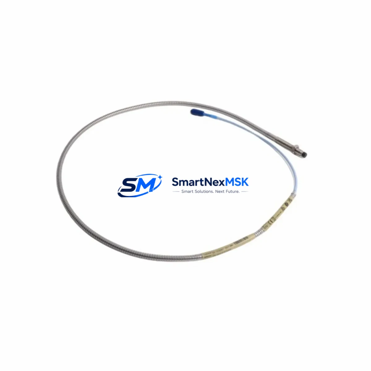
The Bently Nevada 330102-00-96-05-02-05 is an 8mm eddy current proximity transducer engineered for the 3300 XL Series machinery protection platform. As legacy 3300 Series installations reach end-of-service milestones, this transducer serves as the primary retrofit solution for facilities upgrading from discontinued 3300 standard-range probes to the extended-range 3300 XL architecture. It delivers direct mechanical and electrical compatibility with existing conduit runs, junction boxes, and monitor rack wiring, enabling smooth migration without full system teardown.
Industrial sites operating rotating machinery — including steam turbines, compressors, pumps, and gearboxes — rely on the 3300 XL proximity system for continuous shaft vibration and position monitoring. When the original probe or extension cable degrades, or when a plant transitions from an older Bently Nevada 3300 monitor to a current 3500 Series rack, the 330102-00-96-05-02-05 provides a verified drop-in replacement path that preserves existing gap voltage calibration and signal chain integrity.
Upgrade Compatibility Table
| Parameter | Detail |
|---|---|
| SKU / Part Number | 330102-00-96-05-02-05 |
| Series Compatibility | Bently Nevada 3300 XL, 3300, 3500 (with appropriate proximitor) |
| Probe Diameter | 8mm |
| Cable Length | 96 inches (integral cable) |
| Thread Size | M10 x 1.0 |
| Tip Material | Stainless Steel |
| Installation Interface | Direct replacement for 330102 series probes; compatible with 330130 and 330180 extension cables |
| Proximitor Compatibility | 3300 XL 8mm Proximitor (330180), 3500/42M monitor input |
| Communication / Signal | Analog voltage output (–24 VDC bias); compatible with 4–20 mA converters for DCS integration |
| Replacement Recommendation | Direct drop-in for worn or discontinued 330102-00-xx-05-02-05 variants |
| Commissioning Note | Verify gap voltage (–10.0 VDC nominal at 50 mil gap) after installation; recalibrate if replacing across different cable lengths |
| Warranty | 12-Month Warranty — covers manufacturing defects and signal output performance |
Retrofit Planning for Existing Automation Systems
Successful integration of the 330102-00-96-05-02-05 into a running plant begins with a thorough pre-outage audit. Engineers should document the existing probe mounting orientation, conduit routing, and junction box terminal assignments before removal. The integral 96-inch cable on this transducer is designed to reach the proximitor enclosure without splicing in most standard turbine pedestal installations, but sites using longer runs will need to pair it with a 330130-080-00-00 extension cable to maintain signal fidelity.
At the monitor rack, confirm whether the receiving channel is a 3300 XL Proximitor module or a 3500/42M Proximitor I/O module. Both accept the –24 VDC drive voltage and analog gap output from this probe, but the 3500 rack requires the channel to be configured in the System 1 software or Rack Configuration Software (RCS) to match the 8mm transducer sensitivity of 200 mV/mil. If the plant is simultaneously upgrading from a 3300 monitor to a 3500 rack, the I/O module terminal block wiring must be re-mapped: the 3500/42M uses a different pin assignment than the legacy 3300 monitor card, and the shield drain wire must be landed at the proximitor enclosure ground lug rather than the monitor chassis.
For facilities running a DCS such as a Honeywell Experion PKS or Emerson DeltaV, the 4–20 mA output from the 3300 XL Proximitor feeds directly into the DCS analog input card. Verify that the DCS tag scaling matches the new transducer’s linear range (0–90 mil for 8mm probes) and update the HMI faceplate engineering units accordingly. Plants using OSIsoft PI or similar historian platforms should also update the tag descriptor and EU range in the PI point configuration to avoid false alarm conditions during the first post-retrofit run.
When replacing probes on a multi-channel vibration monitoring system, it is common to also inspect and replace the associated 330130 extension cables, the 330180 Proximitor, and the barrier isolators feeding the intrinsically safe zone. Replacing only the probe while leaving aged extension cables in service can introduce impedance mismatches that shift the gap voltage calibration by several hundred millivolts — enough to trigger a false high-vibration alarm or mask a real machinery fault. A complete transducer system replacement — probe, extension cable, and proximitor — is the recommended practice for critical machinery returning from a major overhaul.
For PLC-integrated monitoring applications, the analog output from the proximitor can be wired to a Rockwell Automation 1756-IF16 or similar ControlLogix analog input module. Ensure the module channel is configured for –10 V to +10 V unipolar input range and that the PLC ladder logic scaling block maps the raw counts to engineering units in mils or micrometers. If the plant uses a Siemens S7-300 or S7-400 controller with a SM 331 analog input module, the same signal conditioning principles apply, and the module’s input range must be set to ±10 V via the hardware configuration in STEP 7 or TIA Portal.
Downtime Control During System Migration
Minimizing unplanned downtime during a proximity transducer replacement requires a structured hot-swap protocol. Where process conditions allow, the monitor channel should be placed in bypass mode — using the 3300 or 3500 rack’s channel inhibit function — before the probe is removed. This prevents a spurious trip signal from reaching the ESD system or DCS interlock logic while the transducer is disconnected. The bypass state should be logged in the plant’s Management of Change (MOC) system and communicated to the control room operator before work begins.
Once the new 330102-00-96-05-02-05 is installed and the gap set to the nominal 50 mil (1.27 mm) target, measure the DC gap voltage at the proximitor output terminals with a calibrated multimeter. The expected reading is –10.0 ±0.5 VDC. If the reading falls outside this range, adjust the probe gap in 5 mil increments until the target is achieved. Do not release the channel from bypass until the gap voltage is confirmed stable and the monitor channel has been re-armed in the rack software.
For plants with redundant monitoring channels (X-Y probe pairs), the replacement can often be performed on one axis while the orthogonal channel remains active, providing continuous shaft position data to the control system throughout the procedure. This approach is particularly effective on large steam turbines and centrifugal compressors where a full monitoring blackout is unacceptable. After both channels are restored, perform a slow-roll check at minimum operating speed to verify that the vibration baseline matches the pre-outage trend data stored in the historian.
Retrofit Support FAQ
Q: Is the 330102-00-96-05-02-05 a direct replacement for other 330102 suffix variants?
A: Yes, within the 330102 family, the primary differentiators are cable length (encoded in the third numeric group) and connector type. The -00-96-05-02-05 variant uses a 96-inch integral cable with a standard armored jacket and is mechanically interchangeable with other -05-02-05 connector variants of the same cable length. If replacing a different cable length variant, verify that the total system cable length (probe + extension) remains within the 3300 XL system specification of 5 or 9 meters to maintain calibrated sensitivity.
Q: What pre-shipment testing is performed on this transducer?
A: Each unit undergoes electrical continuity verification, gap voltage output testing at the nominal 50 mil gap, and insulation resistance testing before shipment. A test report is available upon request. The 12-month warranty covers signal output performance and manufacturing defects from the date of invoice.
Q: Can this probe be used with a 3500/42M monitor without a new proximitor?
A: The probe itself is compatible, but the 3500/42M requires a 3300 XL 8mm Proximitor (part 330180-51-05) in the field junction box. If your existing installation uses a 3300 XL Proximitor, it can be retained. If the proximitor is also being replaced as part of the upgrade, ensure the new proximitor’s output cable is routed to the correct 3500/42M I/O module terminal block and that the channel is reconfigured in RCS to reflect the 8mm sensitivity setting.
Q: What is the lead time and are units available from stock?
A: Units are available from current inventory for immediate shipment. Standard lead time for in-stock items is 1–3 business days. For urgent plant shutdowns or emergency replacements, expedited shipping is available. Contact our team to confirm real-time stock levels and arrange priority dispatch.
© 2026 SMARTNEXMSK. All rights reserved.
Original Source: https://smartnexmsk.com
Contact: sales@smartnexmsk.com | +86 18259474341


