Bently Nevada 330102-02-12-20-12-CN Retrofit-Ready Proximity Transducer for 3300 XL Control Systems
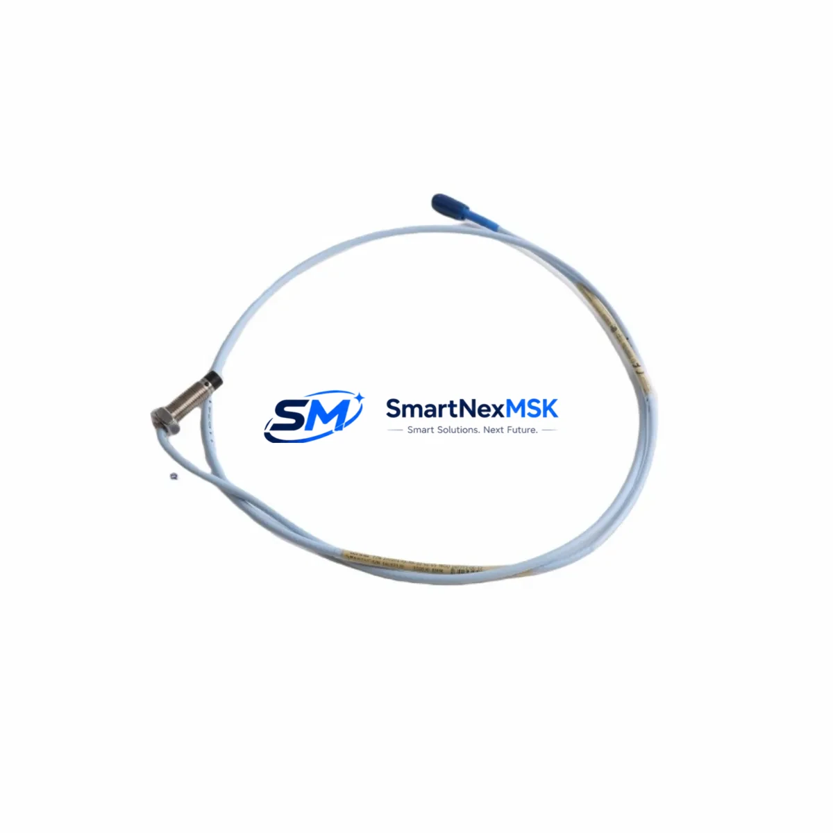
The Bently Nevada 330102-02-12-20-12-CN is a precision eddy-current proximity transducer engineered for seamless integration into Bently Nevada 3300 XL vibration monitoring and machinery protection systems. Designed as a retrofit-ready, drop-in replacement for aging or discontinued transducer assemblies, this unit supports legacy control infrastructure modernization without requiring full system overhaul. Whether you are upgrading a turbine protection panel, replacing a failed sensor in a compressor train, or migrating from an older 3300 Series platform, the 330102-02-12-20-12-CN delivers verified compatibility, reduced commissioning time, and a 12-month warranty backed by pre-shipment functional testing.
This transducer assembly includes a 20-meter extension cable and is calibrated for use with standard Bently Nevada proximitor/driver modules. It is fully compatible with the 3300 XL 8mm Proximitor Sensor ecosystem, making it an ideal candidate for panel retrofits where the original cable routing and conduit infrastructure must be preserved. Engineers replacing worn or damaged transducers in rotating machinery applications — including steam turbines, gas compressors, centrifugal pumps, and gearboxes — will find this unit ready for immediate installation with minimal field adjustment.
Upgrade Compatibility Table
| Parameter | Details |
|---|---|
| SKU / Part Number | 330102-02-12-20-12-CN |
| Brand / OEM | Bently Nevada |
| Compatible System | Bently Nevada 3300 XL Proximity Transducer System |
| Replaces / Supersedes | 330102-02-12-20-12-CN (original), legacy 3300 Series transducer assemblies |
| Cable Length | 20 meters (extension cable included) |
| Probe Tip Diameter | 8 mm |
| Mounting Interface | Standard Bently Nevada threaded probe mount |
| Signal Output | Eddy-current, compatible with 3300 XL Proximitor driver |
| Communication Compatibility | Analog 4–20 mA / voltage output via Proximitor module |
| Installation Requirement | Verify gap voltage (–10 VDC nominal), re-zero after installation |
| Commissioning Note | Confirm probe-to-target gap per OEM specification; recalibrate Proximitor if replacing from different cable length |
| Retrofit Recommendation | Direct drop-in for same cable-length assemblies; re-termination required if replacing different cable variant |
| Warranty | 12 months from shipment date, functional test certificate included |
Retrofit Planning for Existing Automation Systems
Successful integration of the 330102-02-12-20-12-CN into an existing machinery protection architecture requires a structured pre-installation review. Begin by auditing the current Bently Nevada 3300 XL Proximitor/Velomitor module installed in the control cabinet to confirm driver compatibility with the 8mm probe format. In systems where the original transducer was paired with a 3300/16-channel monitor or a 3500/42M Proximitor I/O Module, verify that the channel configuration and alarm setpoints remain valid after the transducer swap — particularly if the replacement cable length differs from the original.
For control cabinets running Bently Nevada 3500 Series rack-based monitoring systems, the 330102-02-12-20-12-CN can serve as a field-side replacement while the rack hardware — including the 3500/20 Rack Interface Module and 3500/22M Transient Data Interface — remains in service. This approach minimizes rack downtime and avoids the cost of full rack replacement. Engineers should also inspect the 3500/15 Power Supply Module to confirm adequate current capacity for the replacement transducer, especially in multi-channel configurations where additional I/O cards have been added over time.
In older installations where the control system communicates via Modbus RTU or RS-232 serial links to a DCS or SCADA platform, the transducer replacement itself does not affect the communication layer — but this is an appropriate time to audit the 3500/92 Communication Gateway Module for firmware currency and protocol mapping accuracy. If the plant is migrating toward Ethernet/IP or PROFIBUS DP integration, consider scheduling the transducer replacement concurrently with a communication module upgrade to reduce total outage windows.
Wiring adaptation is straightforward for same-variant replacements: the probe, extension cable, and Proximitor connector pinout are standardized across the 3300 XL family. However, if the legacy installation used an earlier 330130 or 330180 Series extension cable, verify connector compatibility before installation. Terminal block labeling in the junction box should be documented and photographed prior to disconnection. For systems with a Bently Nevada TK-3 or TK-81 calibration kit on-site, perform a bench gap calibration before field installation to reduce commissioning time at the machine.
HMI screens tied to vibration trend displays — whether running on a System 1 Evolution platform or a third-party SCADA — should be reviewed to confirm that tag names, engineering unit scaling, and alarm thresholds remain consistent after the transducer swap. If the plant uses a GE/Baker Hughes System 1 asset management platform, update the device record to reflect the new serial number and installation date for traceability.
Downtime Control During System Migration
Minimizing unplanned downtime during a transducer replacement on a live rotating machine requires careful sequencing. Where process conditions permit, schedule the swap during a planned maintenance window and coordinate with the control room to place the affected channel in bypass mode on the 3500 Series monitor before disconnecting the probe. This prevents spurious trips during the installation interval and maintains protection on remaining active channels.
Prior to shutdown, export the current channel configuration from the Rack Configuration Software (RCS) and save a backup of all setpoints, scale factors, and OK limit parameters. This ensures that if the replacement transducer requires minor gap adjustment — resulting in a slightly different static output voltage — the original alarm architecture can be restored quickly without re-engineering the protection logic from scratch.
For machines that cannot be taken offline, a hot-swap approach is possible in dual-redundant sensor configurations where a second transducer channel remains active. In this scenario, the failed channel can be replaced while the redundant channel maintains protection continuity. After installation, bring the new transducer online gradually: confirm gap voltage, verify OK status on the monitor front panel, and observe dynamic vibration readings against historical baseline before releasing the bypass. Total field commissioning time for a straightforward same-variant replacement is typically under two hours, including documentation and sign-off.
All units supplied by SMARTNEXMSK undergo pre-shipment functional verification, including gap sensitivity check and cable continuity test, with a test certificate included in the shipment. This reduces on-site commissioning risk and supports rapid return-to-service after replacement.
Retrofit Support FAQ
Q1: Is the 330102-02-12-20-12-CN a direct drop-in replacement for my existing 3300 XL transducer assembly?
A: Yes, provided your existing installation uses the same 8mm probe format and 20-meter cable configuration. If your current assembly uses a different cable length (e.g., 5m or 9m variant), re-termination at the junction box will be required. Confirm the full part number of your existing assembly before ordering to ensure an exact match.
Q2: What commissioning steps are required after installation?
A: After mechanical installation, set the probe-to-target gap to the OEM-specified value (typically 1.0–1.5 mm for 8mm probes, yielding approximately –10 VDC at the Proximitor output). Verify the OK LED status on the monitor module, check dynamic vibration readings against pre-replacement baseline, and confirm alarm setpoints are active. Update the maintenance log and System 1 device record with the new serial number.
Q3: Does this unit support Modbus or Ethernet/IP communication?
A: The transducer itself outputs an analog signal processed by the Proximitor driver module. Digital communication (Modbus RTU, Ethernet/IP, PROFIBUS) is handled at the monitor or gateway level — for example, via the Bently Nevada 3500/92 Communication Gateway. The 330102-02-12-20-12-CN is fully compatible with these architectures as the field-side sensing element.
Q4: What warranty and testing does SMARTNEXMSK provide?
A: Every unit ships with a 12-month warranty from the shipment date. Pre-shipment testing includes gap sensitivity verification, cable continuity check, and connector integrity inspection. A functional test certificate is included with each shipment. For warranty claims or technical support, contact sales@smartnexmsk.com or call +86 18259474341.
© 2026 SMARTNEXMSK. All rights reserved.
Original Source: https://smartnexmsk.com
Contact: sales@smartnexmsk.com | +86 18259474341


