Bently Nevada 330102-02-12-50-01-CN Retrofit-Ready Proximity Probe for 3300 XL Control Systems
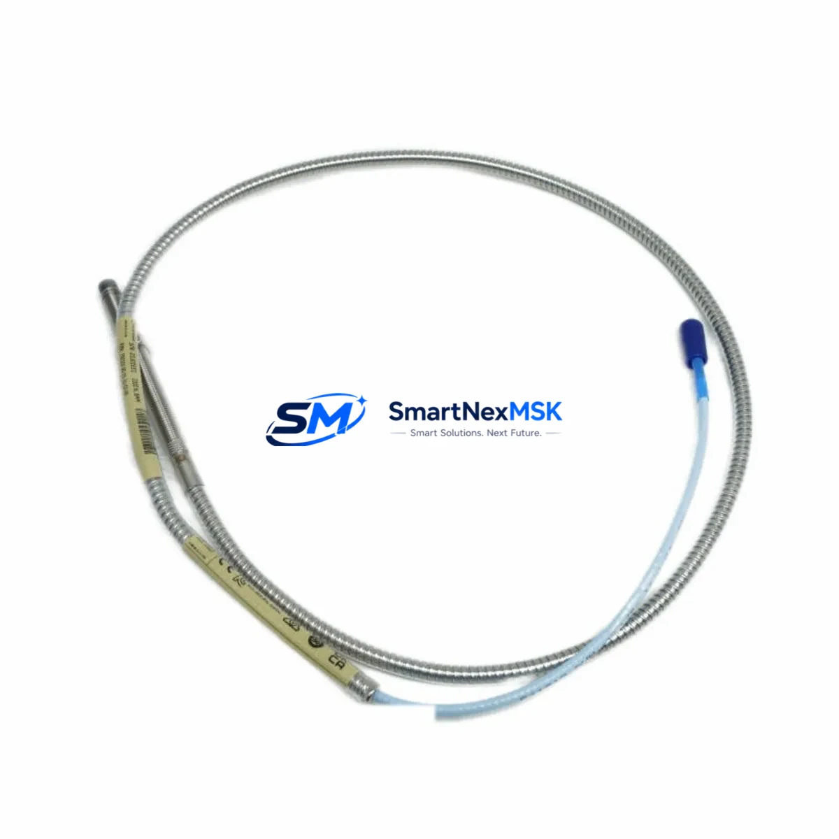
The Bently Nevada 330102-02-12-50-01-CN is an 8mm eddy-current proximity probe engineered for seamless integration into existing 3300 XL Series vibration monitoring systems. As legacy Bently Nevada installations approach end-of-service milestones, this probe serves as a verified drop-in replacement that preserves original signal chain integrity without requiring reprogramming of the monitoring rack or recalibration of the Proximitor® sensor. Whether you are managing a planned outage, responding to an unplanned probe failure, or executing a phased control system upgrade, the 330102-02-12-50-01-CN delivers the dimensional accuracy, output linearity, and environmental rating required for continuous rotating machinery protection.
Upgrade Compatibility Table
| Parameter | 330102-02-12-50-01-CN | Notes |
|---|---|---|
| Probe Diameter | 8 mm | Standard 3300 XL form factor |
| Cable Length | 5.0 m (extension + probe) | Verify total system cable length against Proximitor® driver range |
| Thread | M10 × 1 | Compatible with existing probe holders and brackets |
| Connector Type | 3-pin MIL-spec | Mates directly with 330130 and 330180 extension cables |
| Communication / Signal | Analog DC voltage (–24 VDC bias) | No protocol migration required; direct rack input |
| Replacement Recommendation | Direct swap for 330102-02-12-50-01-CN | No firmware or configuration change needed |
| Commissioning Focus | Gap voltage verification at –10.0 VDC ±0.2 VDC | Confirm with 3300 XL Proximitor® 330180 or 330130 |
| Warranty | 12 Months | Covers manufacturing defects; includes pre-shipment functional test |
Retrofit Planning for Existing Automation Systems
Successful integration of the 330102-02-12-50-01-CN into a running plant begins well before the probe reaches the field. During the planning phase, engineers should audit the full measurement loop: confirm that the installed Proximitor® sensor — typically a 330180-51-05 or 330130-040-01-00 — is within its own service life, since replacing the probe while leaving an aged driver in place can introduce calibration drift that masks the improvement. Extension cables such as the 330130 series must be inspected for jacket integrity and connector pin condition; corroded or intermittent connections are a common source of false high-vibration trips that are often misattributed to the probe itself.
On the rack side, verify that the 3300 XL monitor card — for example a 3300/16 or 3300/20 — has its channel configuration set for the correct probe type and gap range before the new probe is installed. If the plant is running a mixed fleet of 3300 XL and older 3300/05 or 3300/10 monitors, note that the 330102-02-12-50-01-CN is optimized for the XL-generation Proximitor® and may require a companion driver swap on legacy racks. For sites migrating toward the System 1 condition monitoring platform, the probe’s analog output feeds directly into the 3500 Series rack I/O modules without signal conditioning changes, making it a practical bridge component during phased platform transitions.
Power supply integrity is equally critical. The –24 VDC bias supply feeding the Proximitor® should be verified under load; a sagging supply rail — often caused by an aging 3300 XL power supply module — will shift the probe’s output voltage and produce erroneous proximity readings. Where the control cabinet houses multiple measurement loops sharing a common supply, adding a dedicated 3300 XL power supply for the new probe channel eliminates cross-loop interference. Terminal block wiring should follow the original loop drawing exactly: shield drain wire grounded at one end only, signal and return conductors routed away from high-voltage I/O or VFD cabling to prevent induced noise.
For plants operating DCS-integrated machinery protection, confirm that the 3300 XL rack’s 4–20 mA output card — such as the 3300/46 — is correctly scaled for the new probe’s sensitivity factor before the DCS historian begins logging. Incorrect scaling will produce trend data that appears valid but is offset from true shaft position, complicating future bearing wear analysis. All configuration changes should be documented in the site’s MOC (Management of Change) record and verified against the original loop calibration sheet before the unit is returned to service.
Downtime Control During System Migration
Minimizing production loss during a probe replacement requires a structured hot-swap protocol. Where the process permits, place the affected monitor channel in bypass mode within the 3300 XL rack before breaking the probe connection; this prevents a spurious trip signal from propagating to the turbine control system or DCS interlock logic while the probe is disconnected. Keep the original probe and its extension cable intact as a reference assembly — measuring its gap voltage before removal gives you a baseline that the new 330102-02-12-50-01-CN must match within ±0.2 VDC at the same physical gap distance.
Once the new probe is threaded into the holder and the gap is set, power the Proximitor® and confirm the output voltage before reconnecting to the rack. This bench-level check — performed with a calibrated DC voltmeter at the junction box — catches wiring errors and connector faults before the channel is taken out of bypass. After rack reconnection, observe the vibration trend for a minimum of one full shaft rotation cycle to confirm that the signal is clean, free of electrical noise, and tracking correctly against the reference channel on the opposite bearing. Only then should the bypass be removed and the channel returned to its normal trip-and-alarm state. This sequence typically limits total channel downtime to under 30 minutes for a prepared crew, preserving control continuity across the rest of the machinery train.
Retrofit Support FAQ
Q1: Is the 330102-02-12-50-01-CN a direct replacement for my existing 3300 XL probe without any rack reconfiguration?
Yes. The 330102-02-12-50-01-CN is dimensionally and electrically equivalent to the original Bently Nevada specification. No rack card reconfiguration or Proximitor® driver replacement is required provided the existing driver is within its calibrated service range. Gap voltage should be verified after installation as standard commissioning practice.
Q2: What pre-shipment testing is performed on each probe?
Every unit undergoes a functional output linearity test across the full gap range before dispatch. A test certificate confirming sensitivity factor and gap voltage at the nominal operating point is available upon request. The 12-month warranty covers manufacturing defects identified during or after installation.
Q3: Can this probe be used with a 3500 Series rack during a platform migration?
Yes, with the appropriate 3500 Series I/O module configured for the probe’s sensitivity factor. The analog output of the 330102-02-12-50-01-CN is compatible with 3500 rack inputs, making it suitable for sites running parallel 3300 XL and 3500 systems during a phased migration.
Q4: What is the lead time and do you hold stock?
Stock is maintained for immediate dispatch. Standard lead time for in-stock units is 3–7 business days to most destinations. Express shipping options are available for emergency breakdown situations. Contact our team to confirm current inventory levels before placing a critical-path order.
© 2026 SMARTNEXMSK. All rights reserved.
Original Source: https://smartnexmsk.com
Contact: sales@smartnexmsk.com | +86 18259474341


