Bently Nevada 330102-03-25-10-02-05 Maintenance-Ready Spare 3300 XL Automation
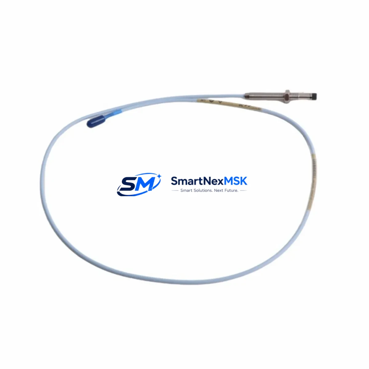
The Bently Nevada 330102-03-25-10-02-05 is an original 8mm eddy-current proximity transducer engineered for the 3300 XL Series continuous machinery monitoring system. Designed for high-reliability rotating machinery applications — including steam turbines, gas compressors, centrifugal pumps, and large induction motors — this transducer delivers precise radial shaft vibration and position measurements critical to predictive maintenance programs and API 670-compliant protection systems.
For maintenance engineers managing aging DCS or vibration monitoring infrastructure, sourcing a verified original spare is the single most important step in minimizing unplanned downtime. The 330102-03-25-10-02-05 ships fully tested against Bently Nevada factory specifications, with dimensional and electrical verification completed prior to dispatch. Each unit is backed by a 12-month warranty covering manufacturing defects and performance conformance.
Whether you are executing a planned turnaround, responding to a high-vibration alarm, or building a critical-spare inventory for a continuous-process facility, this transducer is a direct, drop-in replacement for the original installed component — no recalibration of the monitoring rack is required when the same probe series and cable length are maintained.
Spare Maintenance Table
| Parameter | Specification |
|---|---|
| Part Number | 330102-03-25-10-02-05 |
| Brand | Bently Nevada |
| Series | 3300 XL |
| Sensor Type | Eddy-Current Proximity Transducer |
| Probe Tip Diameter | 8 mm |
| Cable Length | 3 m (integral) |
| Extension Cable | Compatible with 3300 XL Extension Cable series |
| Driver / Proximitor | 3300 XL 8mm Proximitor® (e.g. 330180 series) |
| Measurement Range | 0.25 mm – 2.25 mm (linear range) |
| Scale Factor | 7.87 V/mm (200 mV/mil) |
| Supply Voltage | –24 VDC (nominal) |
| Operating Temperature | –35°C to +177°C (probe tip) |
| Target Material | AISI 4140 steel or equivalent ferromagnetic alloy |
| Compliance | API 670, CE |
| Application | Radial vibration, axial position, differential expansion |
| Compatibility | 3300 XL monitoring racks, 3500 series (with adapter) |
| Condition | Original, factory-tested |
| Warranty | 12 Months |
| Lead Time | In stock — ships within 2 business days |
Maintenance Planning for Continuous Operation
When replacing the 330102-03-25-10-02-05 in the field, a disciplined maintenance engineer will treat the transducer swap as an opportunity to audit the entire vibration monitoring loop. Begin by inspecting the 3300 XL Extension Cable (typically a 330130 or 330180 series cable) for jacket abrasion, connector corrosion, and continuity — a degraded cable is the most common cause of false high-vibration trips after a probe replacement. Verify the 3300 XL Proximitor® module (e.g., 330180-X1-05) output voltage at the monitor rack terminal strip; a drifted Proximitor will invalidate the new probe’s calibration immediately.
At the monitoring rack level, confirm that the 3500/42M Proximitor Monitor or equivalent 3300 rack card is seated correctly and that its OK relay output is healthy. If the machine has been in service for more than five years, consider scheduling a concurrent inspection of the 3300 XL Keyphasor® transducer (e.g., 330980 series) — phase reference integrity is essential for balancing and orbit analysis. For facilities running dual-redundant protection, the paired channel’s probe and cable should be replaced simultaneously to maintain symmetric response.
On the power supply side, check the 3300 XL Power Supply module output for ripple and voltage stability; an under-voltage condition will shift the Proximitor’s gap voltage and produce erroneous readings even with a new probe installed. If the control cabinet houses a Bently Nevada 3500 rack alongside the 3300 XL system, verify that the 3500/15 Power Supply and 3500/20 Rack Interface Module are within specification — cross-system power bus noise can corrupt proximity measurements.
For facilities integrating vibration data into a DCS or safety instrumented system, inspect the signal isolator or barrier (such as a Pepperl+Fuchs or MTL Zener barrier) between the Proximitor output and the DCS analog input card. A degraded barrier will introduce offset errors that appear as slow vibration drift on trend displays. Finally, review the terminal block and field wiring within the junction box for loose terminations, moisture ingress, and shield grounding continuity — these are the most frequently overlooked failure points during routine transducer replacements.
Site Replacement Workflow
Step 1 — Isolation and Lockout: Follow site LOTO procedures. Notify the control room to inhibit the vibration trip for the affected channel before disconnecting the probe.
Step 2 — Gap Measurement: Record the existing probe gap voltage at the Proximitor output terminal (target: –10.0 VDC ±0.5 V for mid-range). This baseline confirms the old probe’s final condition and provides a reference for the new installation.
Step 3 — Probe Removal: Unscrew the probe from the bracket using the correct spanner. Do not apply torque to the cable connector. Inspect the probe tip for impact marks or contamination — document findings for the maintenance record.
Step 4 — New Probe Installation: Thread the 330102-03-25-10-02-05 into the bracket. Set the gap to the system-specified value (typically 1.0 mm / 40 mil for 8mm probes on steel targets). Verify gap voltage at the Proximitor output: –10.0 VDC ±0.2 V confirms correct installation.
Step 5 — System Verification: Re-enable the trip channel. Confirm OK LED status on the Proximitor and the monitor rack. Review the vibration trend for the first 15 minutes of operation to confirm stable baseline readings.
Step 6 — Documentation: Record the replacement in the CMMS with the new part number, gap setting, and post-installation gap voltage. Update the critical-spare inventory to trigger reorder of the consumed unit.
This workflow applies equally to planned turnaround replacements and emergency corrective maintenance, and is compatible with both 3300 XL and legacy 3300 series rack configurations. Maintaining a minimum of one spare 330102-03-25-10-02-05 per monitored machine train is the recommended inventory posture for continuous-process facilities.
Spare Parts Support FAQ
Q1: Is the 330102-03-25-10-02-05 a direct replacement for older 3300 series probes?
Yes. The 3300 XL series maintains backward compatibility with standard 3300 rack configurations when the same cable length and Proximitor model are used. Verify the Proximitor model number on your rack card before installation to confirm scale factor compatibility.
Q2: How is the unit tested before shipment?
Each 330102-03-25-10-02-05 undergoes electrical continuity verification, coil inductance measurement, and gap-voltage output testing against Bently Nevada factory specifications. A test report is available upon request for quality-critical applications.
Q3: What is the recommended spare inventory strategy for this transducer?
For continuous-process plants, maintain one spare per machine train monitored by the 3300 XL system. For facilities with five or more monitored machines, a pooled inventory of two to three units is recommended to cover simultaneous failures during a turnaround event.
Q4: What does the 12-month warranty cover?
The warranty covers manufacturing defects, coil failure, connector integrity, and out-of-specification scale factor performance under normal operating conditions. It does not cover physical damage from improper installation, over-torquing, or target contact. Warranty claims are processed within 5 business days of receipt of the returned unit.
© 2026 SMARTNEXMSK. All rights reserved.
Original Source: https://smartnexmsk.com
Contact: sales@smartnexmsk.com | +86 18259474341


