Bently Nevada 330102-10-40-05-01-00 3300 XL Spare: Precision Replacement for Industrial Downtime Control
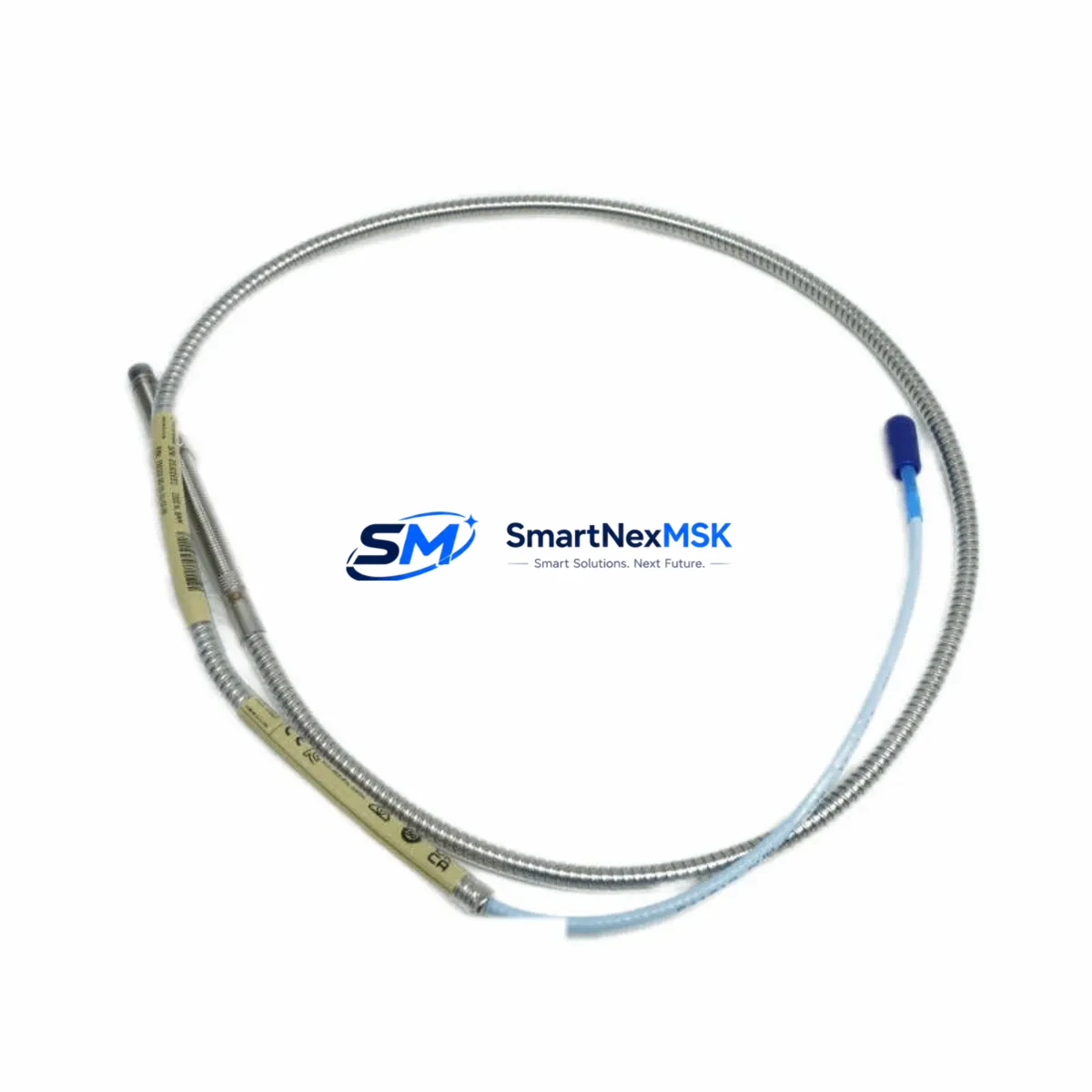
The Bently Nevada 330102-10-40-05-01-00 is an original 8mm eddy-current proximity probe engineered for the 3300 XL Proximity Transducer System. In rotating machinery protection environments — turbines, compressors, pumps, and gearboxes — this probe is a critical front-line sensor. When it fails or degrades, the entire vibration monitoring chain is compromised, triggering unplanned shutdowns and costly downtime. Stocking a verified replacement spare is not optional; it is a fundamental element of any serious predictive maintenance program.
This unit ships fully tested against Bently Nevada factory specifications, with a 12-month warranty covering manufacturing defects. Each probe is inspected for tip condition, cable integrity, connector seating, and output linearity before dispatch. Maintenance engineers can install with confidence, knowing the replacement has been validated prior to arrival on site.
Spare Maintenance Table
| Parameter | Specification |
|---|---|
| Part Number | 330102-10-40-05-01-00 |
| Brand | Bently Nevada |
| Series | 3300 XL Proximity Transducer System |
| Probe Diameter | 8mm |
| Cable Length | 1.0m (probe cable, extension cable ordered separately) |
| Sensing Technology | Eddy-Current (Non-contact) |
| Output Signal | -18 VDC nominal (with matched driver/extension) |
| Compatible Driver | Bently Nevada 3300 XL 8mm Driver (e.g. 330180 series) |
| Compatible Extension Cable | 330130 series (length-matched to total system) |
| Gap Voltage Range | -2 VDC to -18 VDC |
| Linear Range | Approx. 0.25mm – 2.54mm |
| Target Material | AISI 4140 steel or equivalent ferromagnetic alloy |
| Operating Temperature | -35°C to +177°C (probe body) |
| Ingress Protection | Suitable for oil-mist and high-humidity environments |
| Connector Type | Coaxial, factory-terminated |
| Origin | United States |
| Warranty | 12 Months from date of shipment |
| Pre-shipment Test | Output linearity, cable continuity, connector integrity |
Maintenance Planning for Continuous Operation
Replacing the 330102-10-40-05-01-00 probe is rarely an isolated task. A disciplined maintenance engineer treats a probe replacement as an opportunity to audit the entire transducer loop. Begin by verifying the matched 330130 series extension cable — cable length must be consistent with the original system calibration, as any mismatch shifts the gap voltage curve and invalidates the vibration reading. Next, inspect the 330180 series proximitor/driver module seated in the monitor rack; a degraded driver will produce erratic output even with a new probe installed.
Within the same control cabinet, check the 3300 XL monitor card (such as the 3300/16 or 3300/20 series) for alarm setpoint integrity and relay output continuity. Relay output modules — including any 3300/32 relay modules — should be exercised to confirm trip logic is functional before returning the machine to service. If the system feeds a System 1 Evolution or legacy System 1 condition monitoring platform, verify that the channel configuration reflects the correct probe sensitivity constant (typically 7.87 V/mm for 8mm probes).
For installations in high-vibration or high-temperature zones, inspect the probe mounting bracket and armored conduit for mechanical fatigue. Loose probe tip positioning — even by 0.1mm — introduces DC offset errors that can mask real shaft movement. While the cabinet is open, audit the Keyphasor module (e.g., 3300/25 or 330980 series) if one is present; a degraded Keyphasor signal corrupts phase-referenced vibration data across all channels. Also verify the power supply module feeding the monitor rack — Bently Nevada rack systems typically require a stable ±24 VDC supply, and any ripple or sag will affect probe bias voltage and measurement accuracy.
For plants running parallel DCS integration, confirm that the 4–20 mA or digital output from the monitor card is correctly mapped in the DCS I/O module (e.g., Emerson DeltaV or Honeywell Experion input cards). Signal isolation barriers or galvanic isolators between the monitor output and DCS input should be tested for loop integrity. Finally, update the maintenance log with the new probe serial number, installation gap voltage (measured at commissioning), and the date — this baseline is essential for trending and future fault diagnosis.
Site Replacement Workflow
Step 1 — Isolation: Coordinate with operations to place the machine in a safe state. Do not remove the probe under live vibration monitoring without bypassing the trip relay or placing the monitor in bypass mode to prevent spurious shutdowns.
Step 2 — Gap Measurement: Before removing the old probe, record the existing gap voltage using a calibrated voltmeter at the proximitor output. This value serves as the installation target for the replacement unit.
Step 3 — Probe Removal: Unscrew the probe from the mounting bracket carefully. Inspect the probe tip for impact damage or contamination — this often reveals the root cause of failure (shaft rub, oil contamination, or thermal cycling fatigue).
Step 4 — New Probe Installation: Thread the 330102-10-40-05-01-00 into the bracket. Adjust the gap to achieve the target gap voltage (typically -10 VDC ±0.5 VDC for mid-range positioning). Lock the probe with the jam nut once the correct gap is confirmed.
Step 5 — System Verification: Restore the monitor from bypass. Confirm that the vibration reading is within expected baseline range (typically <25 µm pk-pk for a healthy machine at rest). Check that alarm and danger setpoints are active and that relay outputs are armed.
Step 6 — Documentation: Record the new probe part number (330102-10-40-05-01-00), installation gap voltage, technician name, and date in the equipment maintenance record. This supports future predictive maintenance trending and warranty traceability.
This workflow applies equally to planned turnaround replacements and emergency in-service swaps. The 330102-10-40-05-01-00 is a direct form-fit-function replacement for earlier 330102 variants, minimizing re-engineering effort and reducing mean time to repair (MTTR).
Spare Parts Support FAQ
Q1: Is the 330102-10-40-05-01-00 compatible with older 3300 series monitors (non-XL)?
A: The 330102-10-40-05-01-00 is designed and calibrated for the 3300 XL system. While the physical connector may fit older 3300 series hardware, the sensitivity constant and gap voltage curve are optimized for XL-series proximitors. Using it with non-XL drivers may produce calibration offsets. Always verify system compatibility with your instrumentation engineer before installation.
Q2: What is the recommended spare inventory strategy for this probe?
A: For critical rotating machinery (turbines, compressors, main pumps), industry best practice recommends holding a minimum of one spare probe per monitored shaft, plus one additional unit per machine train as a buffer. For plants with 10+ monitored machines, a pooled inventory of 5–10 units reduces emergency procurement lead times and supports rapid response during unplanned outages.
Q3: How is each unit tested before shipment?
A: Every 330102-10-40-05-01-00 unit undergoes pre-shipment inspection covering output linearity verification, cable continuity check, coaxial connector seating integrity, and visual inspection of the probe tip and body. Units that do not meet specification are quarantined. A test report is available upon request for quality-critical applications.
Q4: What does the 12-month warranty cover?
A: The 12-month warranty covers manufacturing defects in materials and workmanship from the date of shipment. It does not cover damage resulting from incorrect installation gap, mechanical impact, chemical contamination, or use outside the specified operating temperature range. Warranty claims are supported with return merchandise authorization (RMA) and replacement dispatch within agreed lead times.
© 2026 SMARTNEXMSK. All rights reserved.
Original Source: https://smartnexmsk.com
Contact: sales@smartnexmsk.com | +86 18259474341


