Bently Nevada 330103-00-02-05-02-05 Retrofit-Ready 3300 XL Proximity Transducer: Compatible Upgrade for Legacy Vibration Monitoring Systems
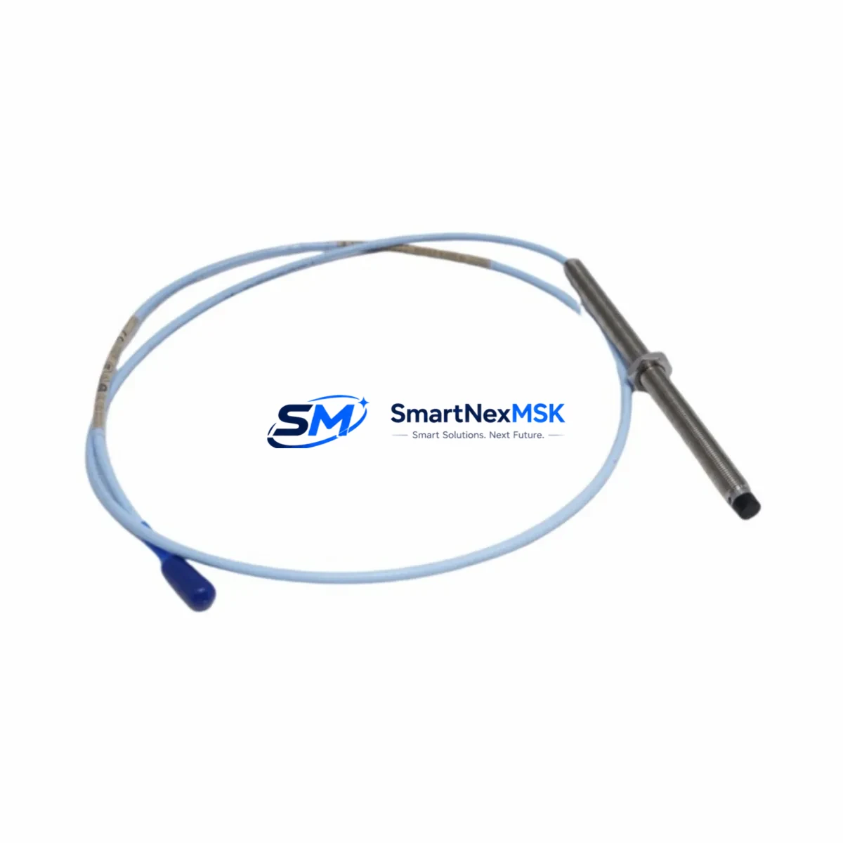
The Bently Nevada 330103-00-02-05-02-05 is an 8mm proximity transducer engineered for the 3300 XL Series continuous vibration monitoring platform. As aging machinery protection systems reach end-of-service milestones, this transducer serves as a verified drop-in replacement for facilities managing rotating equipment across turbines, compressors, pumps, and gearboxes. Whether you are executing a planned outage upgrade, responding to a failed sensor, or modernizing a legacy control cabinet, the 330103-00-02-05-02-05 delivers the signal integrity and dimensional compatibility required for seamless integration into existing 3300 XL monitor racks.
This transducer operates within the standard Bently Nevada proximity system architecture, pairing directly with the 330130 extension cable and the 330180 proximitor/oscillator to form a complete measurement chain. The 8mm tip diameter and 5mm sensing range are consistent with the original factory specification, eliminating the need for bracket modification or re-machining of the observation port. Signal output is a standard -18 VDC bias voltage at the gap center, compatible with all 3300 XL series monitor cards including the 3300/16 and 3300/20 dual-channel vibration monitors.
Upgrade Compatibility Table
| Parameter | 330103-00-02-05-02-05 Specification | Retrofit Notes |
|---|---|---|
| Tip Diameter | 8mm | Direct fit; no bracket modification required |
| Sensing Range | 5mm (0–2mm linear) | Matches OEM gap setting; re-gapping not required if shaft is undisturbed |
| Output Bias Voltage | −18 VDC nominal at center gap | Compatible with all 3300 XL monitor input cards |
| Cable Interface | Armored coaxial, integral 5m cable | Mates with 330130 extension cable; verify connector seating torque |
| Proximitor Compatibility | 330180 Proximitor/Oscillator | No firmware or calibration change required on monitor card |
| Mounting Thread | M10 × 1.0 | Standard thread; inspect bore for corrosion before installation |
| Communication Protocol | Analog (4–20 mA / voltage) | No protocol migration required; signal chain unchanged |
| Monitor Card Compatibility | 3300/16, 3300/20, 3300/46, 3300/55 | Confirm rack slot assignment matches channel address in System 1 software |
| Warranty | 12 Months | Covers manufacturing defects; includes pre-shipment functional test report |
Retrofit Planning for Existing Automation Systems
Successful integration of the 330103-00-02-05-02-05 into a running plant begins well before the maintenance window opens. The first step is a full audit of the existing measurement chain. Technicians should document the current gap voltage on the failed or aging transducer using the 330180 proximitor output terminals, then record the shaft material and surface finish to confirm eddy-current sensitivity factors remain within the calibration curve for this transducer model.
In installations where the 3300 XL rack also houses a 3300/46 Keyphasor monitor or a 3300/55 temperature monitor, care must be taken to avoid disturbing adjacent module seating during transducer cable routing. The 3300 XL backplane uses a passive bus architecture, so module address assignment is determined by physical slot position rather than software configuration — verify that the replacement transducer’s channel maps to the correct slot before closing the cabinet.
For facilities that have already migrated their condition monitoring data to Bently Nevada System 1 software, the transducer replacement requires a point re-verification step within the System 1 database. The measurement point associated with the failed 330103-00-02-05-02-05 must be updated with the new serial number and the as-found gap voltage recorded at commissioning. This ensures that alarm setpoints, trend baselines, and spectrum reference plots remain valid after the swap.
Where the control cabinet also contains a 3500/22M transient data interface or a 3500/42M proximitor monitor from the newer 3500 Series rack, the 330103-00-02-05-02-05 is not directly compatible with those monitor cards without an adapter proximitor. In mixed-generation cabinets, it is common to find both 3300 XL and 3500 Series racks operating in parallel during a phased upgrade. In such cases, the 330103-00-02-05-02-05 continues to serve the legacy 3300 XL channels while the newer 3500/42M handles upgraded measurement points, allowing the plant to maintain full vibration coverage throughout the transition without a full system cutover.
Power supply integrity is a critical pre-check. The 3300 XL rack requires a stable −24 VDC supply rail, typically sourced from a dedicated instrument power supply module within the control cabinet. Before installing the replacement transducer, verify that the supply voltage at the proximitor terminals is within the −22 to −26 VDC tolerance band. A marginal supply voltage is a common root cause of intermittent transducer faults that are misdiagnosed as sensor failures. If the power supply module is original equipment from the same era as the 3300 XL rack, this is an appropriate time to evaluate its replacement as part of the same maintenance scope.
Terminal wiring for the 330103-00-02-05-02-05 follows the standard Bently Nevada three-wire coaxial convention: center conductor (signal), inner shield (return), and outer armor (chassis ground). Confirm that the existing junction box or terminal strip has not developed ground loops introduced by previous repair attempts. A floating ground on the armor can introduce 50/60 Hz noise into the vibration signal, producing false alarm conditions on the 3300/16 monitor card. Use a calibrated insulation resistance tester to verify shield continuity before energizing the new transducer.
Downtime Control During System Migration
Minimizing unplanned downtime during a proximity transducer replacement on a live rotating machine requires a structured hot-swap protocol. Where the process permits a brief coast-down, the preferred approach is to inhibit the affected channel on the 3300 XL monitor card using the front-panel inhibit switch before disconnecting the failed transducer. This prevents a spurious trip signal from propagating to the emergency shutdown system during the cable swap interval.
For installations where the machine cannot be taken offline, a bypass relay or channel inhibit must be coordinated with the control room operator before any wiring is disturbed. Document the inhibit start time in the maintenance log and set a hard time limit — typically 30 minutes for a transducer swap — to ensure the protection gap does not extend beyond the approved window.
Once the 330103-00-02-05-02-05 is installed and the gap voltage is confirmed within the −10 to −18 VDC acceptance band at the proximitor output, remove the channel inhibit and observe the vibration reading for a minimum of five minutes at operating speed before returning the machine to full load. Compare the live spectrum on the System 1 display against the pre-outage baseline to confirm that no structural change has occurred during the maintenance intervention. This step protects both the machine and the validity of the historical trend data stored in the condition monitoring database.
Pre-shipment functional testing is performed on every 330103-00-02-05-02-05 unit before dispatch. Each transducer is verified for output bias voltage, sensitivity factor (V/mm), and cable continuity. A test certificate is included with shipment. The 12-month warranty covers all manufacturing defects identified during installation or normal service, with advance replacement available for critical applications subject to prior arrangement.
Retrofit Support FAQ
Q: Is the 330103-00-02-05-02-05 a direct replacement for the original Bently Nevada part of the same number?
A: Yes. This unit is manufactured to the original dimensional and electrical specification. It is a drop-in replacement requiring no modification to the mounting bore, extension cable, or proximitor. The output sensitivity and bias voltage are matched to the 3300 XL calibration curve.
Q: What commissioning steps are required after installation?
A: After mechanical installation, set the air gap to achieve a bias voltage of −10 to −18 VDC at the proximitor output terminals. Record the as-found gap voltage and update the measurement point record in System 1 software. Verify that the vibration reading is stable and within the expected baseline range before removing the channel inhibit.
Q: Can this transducer be used with a 3500 Series monitor rack?
A: The 330103-00-02-05-02-05 is designed for the 3300 XL monitor architecture. It is not directly compatible with 3500 Series monitor cards such as the 3500/42M without an appropriate proximitor adapter. For 3500 Series applications, a 3300 XL-to-3500 compatible proximitor or a native 3500 Series transducer assembly should be specified.
Q: What does the 12-month warranty cover, and is a test report included?
A: The 12-month warranty covers manufacturing defects in materials and workmanship from the date of shipment. Each unit ships with a pre-shipment functional test report confirming bias voltage, sensitivity, and cable continuity. Warranty claims are processed with advance replacement for critical plant applications subject to prior written arrangement with our sales team.
© 2026 SMARTNEXMSK. All rights reserved.
Original Source: https://smartnexmsk.com
Contact: sales@smartnexmsk.com | +86 18259474341


