Bently Nevada 330103-00-02-05-02-CN Spare 3300 XL: Precision Replacement for Vibration Monitoring Systems
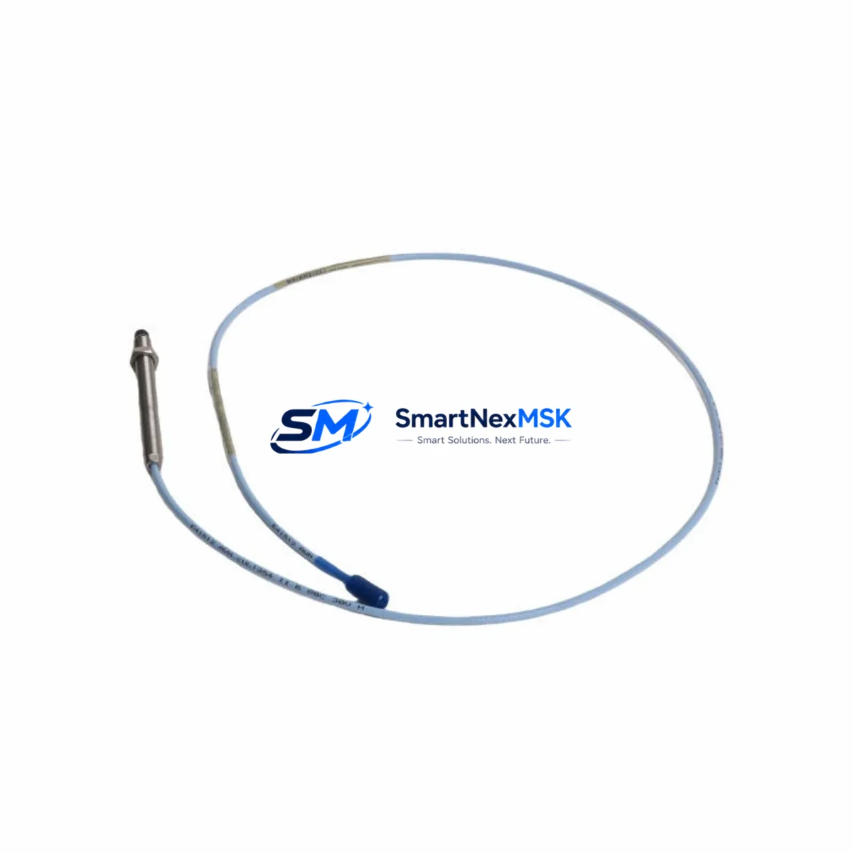
The Bently Nevada 330103-00-02-05-02-CN is an 8mm eddy-current proximity transducer engineered for the 3300 XL Series continuous vibration monitoring platform. In rotating machinery protection systems — turbines, compressors, pumps, and gearboxes — this transducer is a primary sensing element for shaft radial vibration, axial position, and differential expansion measurement. When this component degrades or fails, the entire protection loop is compromised, creating unplanned downtime risk and potential machinery damage. Stocking a verified original spare is the most effective strategy for rapid restoration of monitoring integrity.
This listing supplies a factory-original 330103-00-02-05-02-CN transducer, individually tested prior to shipment, backed by a 12-month warranty, and available for fast international dispatch. Each unit is verified against Bently Nevada 3300 XL system specifications before release.
Spare Maintenance Table
| Parameter | Specification |
|---|---|
| Part Number | 330103-00-02-05-02-CN |
| Brand | Bently Nevada |
| Series | 3300 XL |
| Type | Eddy-Current Proximity Transducer |
| Probe Diameter | 8 mm |
| Cable Length | 2 m (integral) |
| Extension Cable | 3 m (suffix -05) |
| Connector | CN (coaxial, standard) |
| Sensitivity | 7.87 V/mm (200 mV/mil) |
| Linear Range | 0.25 – 2.54 mm (10 – 100 mil) |
| Supply Voltage | -24 VDC (via 3300 XL driver/monitor) |
| Operating Temperature | -35°C to +121°C |
| Compatibility | Bently Nevada 3300 XL Monitor, 3300/16 Monitor, 3500 Series (with appropriate driver) |
| Application | Radial vibration, axial position, differential expansion, eccentricity |
| Installation | Threaded probe mount, 8mm boss, torque to specification |
| Condition | Original, new or recertified — tested before shipment |
| Warranty | 12 Months |
| Origin | USA |
Maintenance Planning for Continuous Operation
Maintenance engineers managing rotating machinery protection systems know that the 330103-00-02-05-02-CN transducer does not operate in isolation. It is one node in a complete measurement chain, and the reliability of the entire chain determines whether the protection system can be trusted. During planned outages or emergency replacements, a disciplined inspection of adjacent components prevents repeat failures and reduces the risk of returning a compromised system to service.
When replacing this transducer, the associated 3300 XL extension cable (typically a 330130-series or 330180-series cable matched to the probe) should be inspected for jacket damage, connector corrosion, and continuity. The 3300 XL proximitor/driver module — commonly a 330180 or 330185 series unit — should be verified for correct output voltage and gap voltage within the linear range, as a degraded driver will cause the new transducer to read incorrectly even if the probe itself is healthy.
At the monitor level, the 3300/16 or 3300 XL monitor card should be checked for alarm setpoint integrity and OK relay status. If the system has experienced a transducer fault, the monitor’s internal diagnostics log should be reviewed before clearing alarms. For sites running the Bently Nevada 3500 Series rack, confirm that the transducer-driver combination is listed in the 3500 system configuration and that the I/O module channel is correctly mapped.
Power supply integrity is equally critical. The 3300 XL power supply module providing -24 VDC to the proximitor circuit should be load-tested and its output ripple verified. A marginal power supply can cause intermittent OK dropouts that mimic transducer failure. Inspect the terminal strip and field wiring in the junction box for loose terminations, moisture ingress, and shield grounding continuity — common causes of noise and false vibration readings in field installations.
For machinery trains with multiple measurement planes, it is good practice to cross-reference the replacement transducer’s gap voltage against adjacent probes on the same shaft to confirm consistent installation depth. Sites using Bently Nevada System 1 software for condition monitoring should update the channel configuration and verify that trend data resumes correctly after the replacement. Where 4–20 mA output isolators or signal conditioners are used to interface the 3300 XL output to a DCS or safety system, these devices should be loop-tested after the transducer swap to confirm end-to-end signal integrity.
Proactive spare parts planning for a 3300 XL-based protection system should include at minimum: one spare transducer per critical measurement plane, one matched extension cable set, one spare proximitor module, and a spare monitor card. Sites with aging infrastructure should also consider stocking a 3300 XL power supply module and a set of coaxial connector adapters to avoid delays caused by connector compatibility issues during emergency repairs.
Site Replacement Workflow
Step 1 — Pre-replacement verification: Confirm the replacement part number 330103-00-02-05-02-CN matches the installed transducer label, cable suffix, and connector type. Verify the extension cable length and proximitor model are compatible with the new transducer. Document the existing gap voltage (typically 10.0 ± 0.5 VDC at mid-gap for 8mm probes) as a baseline for post-installation verification.
Step 2 — Safe isolation: Follow site lock-out/tag-out procedures. For online replacement on non-critical channels, confirm with the control room that the channel can be bypassed in the monitor before disconnecting the field device. Never disconnect a transducer on a trip-active channel without authorization.
Step 3 — Physical installation: Remove the old transducer, clean the probe boss threads, and install the new 330103-00-02-05-02-CN to the manufacturer’s torque specification. Route the integral cable and extension cable with adequate bend radius, avoiding contact with hot surfaces or vibrating structures. Reconnect the coaxial connector at the proximitor, ensuring the connector is fully seated and the locking ring is secure.
Step 4 — Gap setting and verification: With power restored to the proximitor, measure the output voltage at the monitor terminal. Adjust the transducer gap to achieve the target gap voltage per the system configuration. Confirm the monitor channel returns to OK status and that vibration readings are within expected baseline range for the machine at rest or at operating speed.
Step 5 — System restoration: Remove any bypasses, confirm alarm and trip setpoints are active, and document the replacement in the maintenance management system. Update the spare parts inventory to trigger reorder of the consumed transducer.
Spare Parts Support FAQ
Q: Is the 330103-00-02-05-02-CN compatible with both 3300 XL and 3500 Series monitors?
A: The 330103-00-02-05-02-CN is natively designed for the 3300 XL system. It can be used with the 3500 Series when paired with a compatible 3500-series proximitor/driver and the channel is configured accordingly in the 3500 rack software. Always verify the driver-transducer pairing against the Bently Nevada compatibility matrix for your specific 3500 monitor card.
Q: How is each unit tested before shipment?
A: Every 330103-00-02-05-02-CN unit is bench-tested for output sensitivity, linear range, and OK status prior to dispatch. Units are packaged with anti-static protection and include a test record. The 12-month warranty covers manufacturing defects and performance deviations from published specifications.
Q: What is the recommended spare parts stocking strategy for this transducer?
A: For critical rotating machinery (turbines, compressors, large pumps), maintain a minimum of one spare transducer per measurement plane, plus one spare extension cable set and one spare proximitor module per protection rack. For non-critical machinery, a shared pool of two to three transducers per site is typically sufficient for planned maintenance cycles.
Q: Can this transducer replace older 330103 variants with different suffixes?
A: The suffix structure of the 330103 series encodes probe diameter, cable length, extension cable length, and connector type. The -00-02-05-02-CN variant specifies an 8mm probe, 2m integral cable, 5m extension, and CN connector. Substitution with a different suffix is possible only if the physical dimensions, cable lengths, and connector type are compatible with the installation. Confirm all suffix parameters before ordering a cross-suffix replacement.
© 2026 SMARTNEXMSK. All rights reserved.
Original Source: https://smartnexmsk.com
Contact: sales@smartnexmsk.com | +86 18259474341


