Bently Nevada 330103-00-03-10-12-00 Spare 3300 XL Automation: Precision Spare for Vibration Monitoring Downtime Control
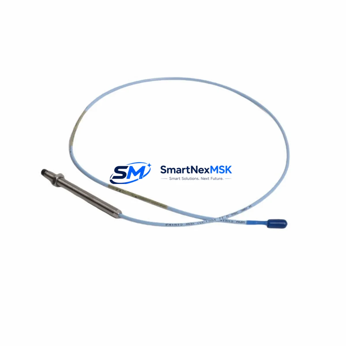
The Bently Nevada 330103-00-03-10-12-00 is an 8mm proximity transducer engineered for the 3300 XL Series continuous vibration monitoring system. In rotating machinery protection — turbines, compressors, pumps, and gearboxes — this transducer is the primary sensing element that feeds shaft displacement data to the monitor rack. When this component degrades or fails, the entire vibration channel goes blind, exposing critical assets to undetected mechanical faults and potential catastrophic failure.
For maintenance engineers managing planned outages or responding to unplanned trips, having a verified, tested replacement unit on the shelf is not optional — it is a core element of any credible spare parts strategy. This listing provides an original-specification 330103-00-03-10-12-00 transducer, fully tested prior to dispatch, backed by a 12-month warranty, and ready for immediate site installation.
Spare Maintenance Table
| Parameter | Specification |
|---|---|
| Part Number | 330103-00-03-10-12-00 |
| Brand | Bently Nevada |
| Series | 3300 XL |
| Transducer Type | 8mm Proximity Transducer |
| Measurement | Radial shaft vibration, axial position, differential expansion |
| Cable Length | 3m integral cable (suffix -03) |
| Extension Cable | Compatible with 330130 series extension cables (5m, 9m) |
| Driver / Proximitor | 3300 XL 8mm Proximitor Sensor (330180 series) |
| Target Material | Steel / Iron (AISI 4140 reference) |
| Operating Temperature | -35°C to +120°C |
| Sensitivity | 7.87 V/mm (200 mV/mil) |
| Linear Range | 0.25 mm to 2.54 mm (10 to 100 mil) |
| Supply Voltage | -24 VDC (via Proximitor) |
| Connector | 3-pin MIL-C-5015 style |
| Mounting Thread | M10 x 1.0 |
| IP Rating | IP67 |
| Compatibility | 3300 XL Monitor Racks, 3500 Series (with correct Proximitor) |
| Application | Turbines, compressors, pumps, motors, gearboxes |
| Warranty | 12 Months from date of shipment |
| Pre-shipment Test | Full electrical and sensitivity verification |
| Origin | USA |
Maintenance Planning for Continuous Operation
Replacing the 330103-00-03-10-12-00 transducer in the field is rarely an isolated task. A disciplined maintenance engineer will treat this replacement as an opportunity to inspect the entire vibration monitoring loop and adjacent control cabinet components. The 330130 series extension cable connecting the transducer to the Proximitor should be inspected for jacket damage, connector corrosion, and continuity — a degraded cable is a common source of false readings that can be misattributed to the transducer itself.
The 330180 series 3300 XL 8mm Proximitor Sensor is the active driver for this transducer and should be verified for correct bias voltage output (typically -10.0 VDC at mid-gap) and gap voltage linearity. If the Proximitor is original to the installation and has not been replaced within the last 10 years, consider stocking a spare unit alongside the transducer. The 3300 XL monitor card — such as the 3300/16 or 3300/20 dual-channel monitor — should be checked for alarm setpoint integrity and channel OK status after transducer replacement.
Within the control cabinet, inspect the 24 VDC power supply rail feeding the Proximitor. A sagging or noisy DC supply will introduce measurement error that persists even after a new transducer is installed. Terminal blocks on the signal wiring should be checked for looseness and oxidation, particularly in high-vibration or high-humidity environments. If the installation uses a signal isolator or barrier between the Proximitor output and the DCS input card, verify that the isolator — such as a HART-compatible signal conditioner or a galvanic isolator module — is within its calibration interval.
For plants running 3500 Series racks alongside legacy 3300 XL hardware, confirm that the Proximitor model and gap voltage range are compatible with the monitor card’s input specification before installation. Mixing 5mm and 8mm Proximitor-transducer pairs is a common field error that produces out-of-range gap voltages and nuisance trips. Keep a laminated compatibility matrix inside the cabinet door as a quick reference for maintenance technicians.
Where the vibration channel feeds a safety instrumented system (SIS) or emergency shutdown (ESD) logic, coordinate the replacement with the safety team and follow the site’s management of change (MOC) procedure. After installation, perform a functional test by introducing a known gap change and verifying that the monitor card responds correctly before returning the machine to service.
Site Replacement Workflow
Step 1 — Isolation and Permit: Obtain a work permit and confirm the machine is in a safe state. For online replacement on non-trip-critical channels, confirm bypass status on the monitor rack before disconnecting the transducer.
Step 2 — Cable Disconnection: Disconnect the 330130 extension cable at the Proximitor end. Label the cable with the channel designation before removal to prevent cross-connection errors during reinstallation.
Step 3 — Transducer Removal: Using the correct spanner for the M10 x 1.0 thread, back out the old 330103-00-03-10-12-00 transducer. Note the gap setting (number of exposed threads) for reference when installing the replacement.
Step 4 — Inspection: Inspect the transducer bore, target area on the shaft, and the extension cable connector for contamination, mechanical damage, or corrosion. Clean as required before installing the new unit.
Step 5 — Installation and Gap Setting: Thread the replacement transducer into the bracket. Set the gap to the manufacturer’s recommended value (typically 1.0 mm / 40 mil for 8mm probes on steel targets) using a non-ferrous feeler gauge. Verify bias voltage at the Proximitor output is within the linear range (-10.0 ± 0.5 VDC).
Step 6 — Functional Verification: Remove the bypass, confirm the monitor card shows a valid OK status, and verify that vibration readings are within expected baseline values for the machine at its current operating condition.
Step 7 — Documentation: Record the replacement in the CMMS, update the spare parts inventory, and note the as-found gap voltage and as-left gap voltage for trending purposes.
Spare Parts Support FAQ
Q: Is the 330103-00-03-10-12-00 compatible with both 3300 XL and 3500 Series monitor racks?
A: The transducer itself is mechanically and electrically compatible with both systems when paired with the correct 8mm Proximitor. However, the 3500 Series uses a different Proximitor model (3500/42 or similar) with a different gap voltage specification. Always verify the Proximitor model and gap voltage range against the monitor card’s input specification before installation.
Q: What is the recommended spare parts stocking strategy for this transducer?
A: For critical rotating machinery, a minimum of one spare transducer per monitored machine train is recommended, with an additional unit held at the plant warehouse for multi-train facilities. Given the 3300 XL system’s age in many installations, stocking a matched set — transducer, extension cable, and Proximitor — reduces the risk of a single-component failure extending downtime.
Q: How is the unit tested before shipment?
A: Each 330103-00-03-10-12-00 unit undergoes full electrical verification including DC resistance, sensitivity check against a reference target, and bias voltage output confirmation. A test report is available upon request. Units that do not meet original specification are not dispatched.
Q: What does the 12-month warranty cover?
A: The warranty covers manufacturing defects and electrical performance failures under normal operating conditions for 12 months from the date of shipment. It does not cover damage resulting from incorrect installation, mechanical impact, or operation outside the specified environmental limits. Warranty claims are supported with direct technical assistance and expedited replacement dispatch.
© 2026 SMARTNEXMSK. All rights reserved.
Original Source: https://smartnexmsk.com
Contact: sales@smartnexmsk.com | +86 18259474341


