Bently Nevada 330103-00-04-15-02-00 Retrofit-Ready Proximity Transducer for 3300 XL Control Systems
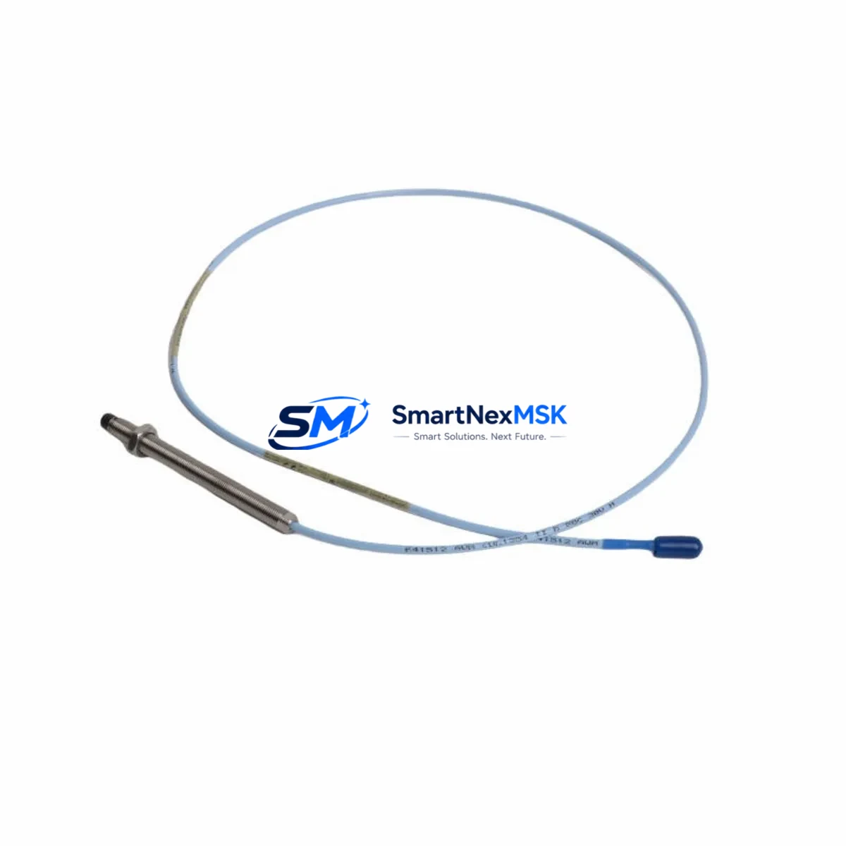
The Bently Nevada 330103-00-04-15-02-00 is an 8mm proximity transducer engineered for the 3300 XL Series vibration monitoring platform. As legacy machinery protection systems age and OEM support windows close, this unit serves as a direct retrofit replacement for facilities managing rotating equipment across power generation, oil & gas, petrochemical, and heavy industrial environments. Whether you are replacing a failed transducer on a critical compressor train, upgrading a turbine monitoring loop, or restoring a dormant machinery protection channel, the 330103-00-04-15-02-00 delivers the dimensional, electrical, and signal compatibility required for a smooth, low-downtime changeover.
This transducer operates within the standard Bently Nevada 3300 XL signal chain, interfacing directly with the 3300 XL Extension Cable and the 3300 XL Proximitor Sensor to deliver a calibrated output to the 3500/40M Proximitor/Seismic Monitor or the 3500/42M Proximitor/Seismic Monitor rack-mounted modules. Engineers replacing units in existing 3500 Series racks should verify that the Proximitor driver card sensitivity setting (typically –7.87 V/mm or –200 mV/mil) matches the replacement transducer’s calibration range before energizing the loop.
Upgrade Compatibility Table
| Parameter | 330103-00-04-15-02-00 Specification | Retrofit Notes |
|---|---|---|
| Transducer Type | 8mm Eddy-Current Proximity | Direct drop-in for 3300 XL 8mm series |
| Cable Length | 5m (integral) | Match with 3300 XL Extension Cable for total system length |
| Thread / Mounting | M10 × 1 threaded body | Verify bracket bore; no machining required for standard mounts |
| Output Sensitivity | –200 mV/mil (–7.87 V/mm) | Confirm Proximitor driver card sensitivity before loop energization |
| Communication / Signal | Analog DC voltage (–24 VDC bias) | Compatible with 3500/40M and 3500/42M monitor modules |
| Replacement Compatibility | 330103-00-04-15-02-00 (OEM equivalent) | Replaces worn, failed, or discontinued OEM units |
| Commissioning Requirement | Gap voltage verification at –10 to –12 VDC | Use Bently Nevada gap tool or calibrated DMM at terminal block |
| Warranty | 12-Month Warranty | Covers manufacturing defects; includes pre-shipment functional test |
Retrofit Planning for Existing Automation Systems
Successful integration of the 330103-00-04-15-02-00 into an aging machinery protection system requires a structured pre-installation audit. Begin by documenting the existing wiring at the JB (junction box) terminal block, noting the shield drain routing and the polarity of the coaxial cable connecting the transducer to the 3300 XL Extension Cable. In many field installations, the extension cable — typically a 3300 XL 5m or 9m armored extension — shows insulation degradation before the transducer itself fails; replacing both simultaneously eliminates a common callback cause.
At the rack level, confirm that the 3500 Series chassis backplane is supplying a stable –24 VDC to the Proximitor channel. Voltage sag on the backplane power bus, often caused by a degraded 3500/15 Power Supply module, can produce false gap alarms even after a transducer swap. If the rack houses a 3500/20 Rack Interface Module, verify that the system configuration stored in the RIM still reflects the correct transducer type and gap range before downloading to the monitor.
For facilities running a dual-channel radial vibration loop — common on large centrifugal compressors — both the X-axis and Y-axis transducers should be replaced as a matched pair to maintain consistent sensitivity across the measurement plane. The companion transducer in a typical 3300 XL dual-probe arrangement is often a 330103-00-04-10-02-00 (3m cable variant) or a 330180-91-00 Proximitor Sensor, depending on the original system design. Confirm the part numbers stamped on the existing Proximitor housing before ordering to avoid sensitivity mismatches.
Where the control system integrates vibration data into a DCS or safety instrumented system via a 3500/92 Communication Gateway Module, verify that the Modbus or FOUNDATION Fieldbus address map for the affected channel remains unchanged after the transducer replacement. A channel address shift caused by an inadvertent rack reconfiguration can corrupt the historian trend and trigger nuisance alarms at the DCS operator station. Coordinate with the control room team to place the affected channel in bypass mode — using the 3500 rack’s front-panel keyswitch or the System 1 software — before breaking the transducer connection.
All units are pre-shipment tested for gap linearity, sensitivity, and insulation resistance. Stock is available for immediate dispatch, supporting both planned turnaround outages and emergency breakdown scenarios. 12-month warranty is included as standard.
Downtime Control During System Migration
Minimizing unplanned downtime during a proximity transducer replacement on a live rotating machine requires careful sequencing. The recommended approach is to place the affected monitor channel into Alert/Danger bypass via the 3500 rack keyswitch before disconnecting the transducer, preventing a spurious trip signal from propagating to the ESD (Emergency Shutdown) system or the turbine control panel.
Once the new 330103-00-04-15-02-00 is installed and the gap voltage is confirmed within the –10 to –12 VDC window using a calibrated digital multimeter at the Proximitor output terminals, the bypass can be lifted and the channel returned to normal monitoring. The entire hot-swap procedure — from bypass engagement to channel restoration — typically takes under 30 minutes for a trained instrumentation technician familiar with the 3500 Series rack architecture.
For facilities where the vibration data feeds a Safety Instrumented Function (SIF) with a defined SIL rating, the bypass period must be logged and managed in accordance with the site’s Management of Change (MOC) procedure. Retain the pre-installation and post-installation gap voltage readings as commissioning records. These records also serve as the baseline for the next scheduled calibration interval, reducing future diagnostic time.
Where a full rack migration from a legacy 3300 Series to a 3500 Series platform is planned, the transducer and extension cable assemblies are typically reusable, as the 3300 XL signal chain is forward-compatible with 3500 Series Proximitor monitor cards. This compatibility significantly reduces the hardware scope — and therefore the outage window — of a rack modernization project.
Retrofit Support FAQ
Q1: Is the 330103-00-04-15-02-00 a direct replacement for the original Bently Nevada OEM part?
A: Yes. This unit is manufactured to the same dimensional, electrical, and sensitivity specifications as the original 330103-00-04-15-02-00. It is a drop-in replacement requiring no modification to the existing mounting bracket, extension cable, or Proximitor driver card settings, provided the existing system was originally configured for the standard 8mm, –200 mV/mil sensitivity specification.
Q2: What gap voltage should I set after installation?
A: The nominal gap voltage for the 330103-00-04-15-02-00 in a standard 3300 XL installation is –10 to –12 VDC, measured at the Proximitor output terminals with the target shaft stationary and centered in the bearing. Use a calibrated DMM and refer to the Bently Nevada installation drawing for the specific shaft material correction factor if the target is not AISI 4140 steel.
Q3: Does this transducer require any firmware or software changes in the 3500 rack?
A: No firmware changes are required. The 3500 Series monitor configuration (transducer type, sensitivity, gap range) is stored in the 3500/20 Rack Interface Module. As long as the replacement transducer matches the original specification, no System 1 or Rack Configuration Software (RCS) download is needed. Verify the existing configuration has not drifted before lifting the bypass.
Q4: What warranty and pre-shipment testing is included?
A: Every unit ships with a 12-month warranty covering manufacturing defects and is subjected to a pre-shipment functional test including gap linearity verification, sensitivity check, and insulation resistance measurement. Test records are available upon request and can be included with the shipment documentation for your site QA file.
© 2026 SMARTNEXMSK. All rights reserved.
Original Source: https://smartnexmsk.com
Contact: sales@smartnexmsk.com | +86 18259474341


