Bently Nevada 330103-00-05-20-02-00 Spare for 3300 XL Automation: Spare Replacement & Industrial Downtime Risk Control
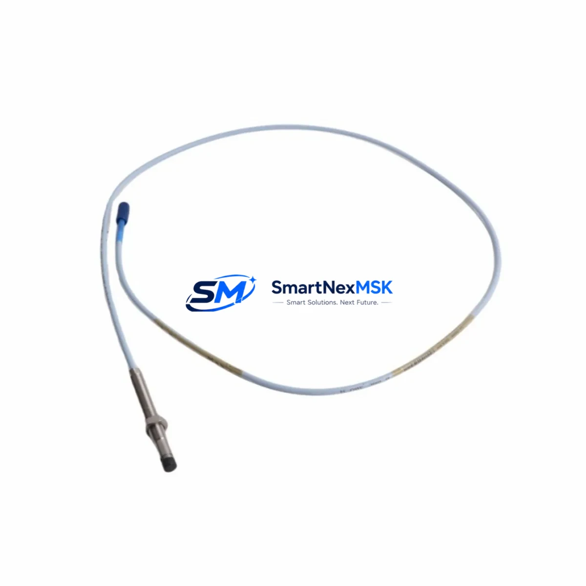
The Bently Nevada 330103-00-05-20-02-00 is an original 8mm eddy-current proximity transducer engineered for the 3300 XL Series continuous vibration monitoring system. In rotating machinery protection — turbines, compressors, pumps, and gearboxes — this transducer is the primary sensing element that converts shaft displacement into a calibrated voltage signal. When this component degrades or fails, the entire vibration channel goes blind, leaving critical rotating assets unprotected and exposing the facility to unplanned shutdown, cascade damage, and costly emergency repairs.
Sourced directly from authorized supply chains, this spare is tested, serialized, and shipped with full documentation. It is a direct maintenance-ready replacement for aging or failed units in legacy and active 3300 XL installations, with no firmware changes or recalibration of the monitoring rack required when installed within the original system architecture.
Spare Maintenance Table
| Parameter | Specification |
|---|---|
| Part Number | 330103-00-05-20-02-00 |
| Brand | Bently Nevada |
| Series | 3300 XL |
| Type | 8mm Eddy-Current Proximity Transducer |
| Sensitivity | 7.87 V/mm (200 mV/mil) |
| Linear Range | 0.25 mm – 2.54 mm (10–100 mil) |
| Supply Voltage | -24 VDC (nominal) |
| Output Signal | DC voltage proportional to gap distance |
| Cable Length | 5m (integral) |
| Extension Cable Compatibility | 330130 Series (3m, 5m, 9m) |
| Driver/Proximitor Compatibility | 330180 Proximitor Sensor |
| Temperature Range | -35°C to +177°C (probe tip) |
| Target Material | AISI 4140 steel or equivalent ferromagnetic alloy |
| Ingress Protection | IP67 (connector end) |
| Installation Thread | M10 × 1.0 |
| Origin | USA |
| Warranty | 12 Months |
| Condition | Original, New / Tested Surplus |
Maintenance Planning for Continuous Operation
When a maintenance or reliability engineer schedules replacement of the 330103-00-05-20-02-00 transducer, the scope of inspection should extend beyond the probe itself. The 3300 XL vibration channel is a system — every element in the signal chain contributes to measurement accuracy and trip reliability.
Begin with the 330180 Proximitor Sensor (driver module), which conditions the raw transducer signal into the calibrated output consumed by the monitor. A degraded Proximitor can produce offset voltages or erratic OK relay behavior even with a new probe installed. Inspect the Proximitor’s supply voltage input and verify the OK output relay is functioning correctly before closing the cabinet.
Next, audit the 330130 Series extension cable connecting the transducer to the Proximitor. Extension cables are frequently damaged by heat, vibration fatigue, or mechanical abrasion in turbine enclosures. A cracked shield or intermittent conductor will introduce noise into the gap voltage signal, causing false high-vibration alarms or masking real shaft movement.
At the monitor rack level, inspect the 3300/16 or 3300/20 Series monitor card for the affected channel. Verify the channel’s OK status, alarm setpoints, and trip multiplier settings have not drifted. If the monitor card has been in service for more than 10 years, consider stocking a spare card alongside the transducer to reduce mean time to repair during an emergency.
The 3300/05 Power Supply module feeding the Proximitor rail deserves attention during any planned outage. Proximitor sensors are sensitive to supply voltage ripple; a failing power supply can cause intermittent OK dropouts that are difficult to diagnose under load. Measure the -24 VDC rail under full channel load and compare against the module’s specification.
For installations where the 3300 XL rack communicates with a DCS or safety system via 4–20 mA output cards or relay output modules, verify that the analog output scaling and the relay trip setpoints remain consistent with the current machine protection philosophy. A transducer replacement is an ideal checkpoint to confirm that no setpoint drift has occurred since the last formal review.
In control cabinets housing multiple 3300 XL channels — common in large compressor trains or steam turbine packages — also inspect terminal blocks, cable ferrules, and grounding bars. Loose terminations on the Proximitor signal wiring are a leading cause of intermittent vibration readings that are misdiagnosed as transducer failure. Torque all terminations to specification and verify shield grounding is single-point at the Proximitor end.
Where the vibration system interfaces with a GE Bently Nevada System 1 or Orbit software platform, confirm that the channel configuration database reflects the new transducer’s serial number and calibration data. Maintaining accurate asset records in the condition monitoring software ensures that trend data remains valid across the component replacement event.
Finally, for facilities managing aging 3300 XL installations approaching end-of-support, consider establishing a minimum stock level of two 330103-00-05-20-02-00 transducers per machine train, paired with one spare 330180 Proximitor and one spare extension cable set. This three-component kit covers the most common field-replaceable elements and supports a sub-four-hour channel restoration target during an unplanned outage.
Site Replacement Workflow
Step 1 — Isolation & Lockout: Follow site LOTO procedures. De-energize the Proximitor supply rail for the affected channel at the 3300/05 power supply. Do not remove the transducer under live supply — the Proximitor OK relay will drop, which may trigger a spurious alarm or trip if the monitor is in trip-enabled mode.
Step 2 — Gap Measurement & Documentation: Before removing the old transducer, record the installed gap voltage from the monitor front panel or System 1 display. Note the physical gap dimension using a feeler gauge if accessible. This baseline allows you to set the replacement transducer to the same operating point without a full recalibration run.
Step 3 — Transducer Removal: Unscrew the 330103-00-05-20-02-00 from the bracket using the M10 × 1.0 thread. Inspect the bracket bore for fretting, corrosion, or thread damage. Clean and re-tap if necessary before installing the replacement.
Step 4 — Replacement Installation: Install the new 330103-00-05-20-02-00. Set the gap to the documented baseline (typically 1.0–1.5 mm for most 3300 XL applications, confirm against the original machine datasheet). Reconnect the extension cable and verify the connector is fully seated and locked.
Step 5 — Channel Verification: Re-energize the Proximitor supply. Confirm the OK LED illuminates and the gap voltage on the monitor channel matches the target value ±0.5 VDC. Verify the channel is not in alarm or trip state before returning the machine to service.
Step 6 — Documentation & Spare Replenishment: Log the replacement in the CMMS with the new transducer serial number, installation date, and gap setting. Immediately initiate a purchase order to replenish the consumed spare and restore the minimum stock level.
Spare Parts Support FAQ
Q: Is the 330103-00-05-20-02-00 a direct drop-in replacement for older 330103 variants?
A: Yes. The 330103-00-05-20-02-00 is backward compatible with all 3300 XL 8mm transducer mounting brackets and 330180 Proximitor Sensors. No changes to the monitor card configuration are required when replacing like-for-like within the 3300 XL architecture. Always verify the extension cable part number matches the replacement transducer’s integral cable length to maintain the calibrated system sensitivity of 7.87 V/mm.
Q: What pre-shipment testing is performed on this spare?
A: Each unit undergoes electrical continuity verification, insulation resistance testing, and gap-voltage output confirmation against the published sensitivity specification before dispatch. Units are individually packaged with anti-static protection and shipped with a test report. The 12-month warranty covers manufacturing defects and out-of-specification performance from the date of delivery.
Q: How should this spare be stored to maintain its service life?
A: Store in a dry, temperature-controlled environment between -20°C and +70°C, away from strong magnetic fields and mechanical vibration. Keep the connector end capped with the supplied protective cover. Inspect stored units annually for cable jacket integrity and connector pin condition. Rotate stock on a first-in, first-out basis to ensure the oldest unit is deployed first.
Q: What is the lead time and can expedited shipping be arranged for emergency breakdowns?
A: Standard orders ship within 1–3 business days after payment confirmation. For emergency breakdown situations, contact the sales team directly to arrange same-day or next-flight-out dispatch. Expedited freight options including air courier are available to most industrial regions. Provide your site location and urgency level when contacting us to receive a tailored logistics solution.
© 2026 SMARTNEXMSK. All rights reserved.
Original Source: https://smartnexmsk.com
Contact: sales@smartnexmsk.com | +86 18259474341


