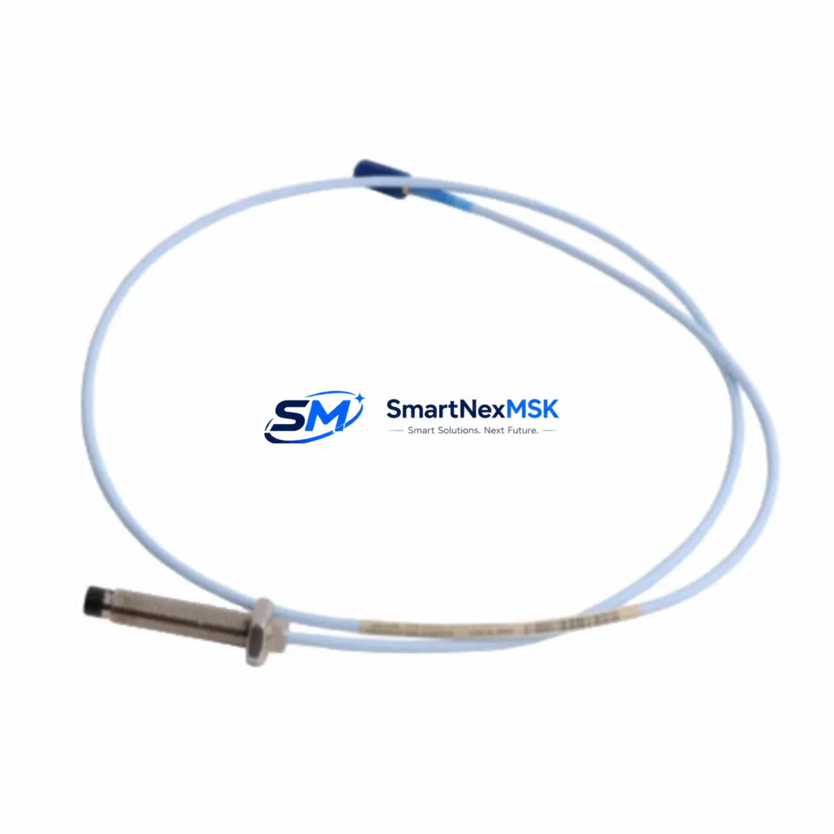
Bently Nevada 330103-00-06-05-02-00 Retrofit-Ready Proximity Probe for 3300 XL Control Systems
The Bently Nevada 330103-00-06-05-02-00 is an 8mm proximity probe engineered for seamless integration into existing 3300 XL Series vibration monitoring systems. As legacy Bently Nevada 3300 Series installations approach end-of-life or require spare-part replenishment, this probe serves as a verified drop-in replacement that preserves original wiring topology, calibration coefficients, and signal chain integrity — eliminating the need for costly system-wide overhauls.
Whether you are managing a planned outage, responding to an unplanned probe failure, or executing a phased modernization of your rotating machinery protection infrastructure, the 330103-00-06-05-02-00 delivers the dimensional accuracy, sensitivity range, and connector compatibility required to restore full system functionality with minimal engineering intervention.
Upgrade Compatibility Table
| Parameter | Details |
|---|---|
| Probe Diameter | 8mm |
| Compatible Series | Bently Nevada 3300 XL, 3300 NSv, 3500 Series (with adapter) |
| Connector Type | Standard BNC / MIL-spec coaxial — matches OEM wiring harness |
| Cable Length | 0.5m integral cable (extension cable 330130-045-00-CN compatible) |
| Sensitivity | 7.87 V/mm (200 mV/mil) — factory calibrated |
| Gap Voltage Range | −10 VDC to −18 VDC |
| Installation | Direct mount — no bracket modification required for 3300 XL housings |
| Communication Compatibility | Analog signal output; compatible with 3300 XL monitor rack I/O cards |
| Replacement Recommendation | Direct replacement for discontinued 330103-00-06-05-00-00 and 330103-00-06-05-01-00 |
| Commissioning Notes | Verify gap voltage at −12 VDC ±0.5 V; re-enter calibration factor in monitor card if replaced mid-run |
| Warranty | 12 Months — covers manufacturing defects, sensitivity drift, and connector integrity |
Retrofit Planning for Existing Automation Systems
Successful integration of the 330103-00-06-05-02-00 into a legacy control environment requires a structured pre-installation review. Begin by auditing the existing 3300 XL monitor rack to confirm available I/O card slots and verify that the installed 3300/16-24-01-01-00 proximitor/Seismic Interface Module is compatible with the probe’s output impedance. In most 3300 XL installations, the proximitor is mounted in a dedicated enclosure adjacent to the machinery; confirm that the existing 330130 extension cable length is sufficient to reach the new probe tip without splicing.
For sites running mixed-generation hardware — for example, a control cabinet that houses both 3300 XL vibration monitors and a 3500/22M Transient Data Interface — confirm that the analog signal from the 330103-00-06-05-02-00 is routed to the correct channel on the 3500/42M Proximitor/Seismic Monitor before energizing. Mislabeled terminal blocks are a common source of commissioning delays in retrofit projects.
If the site is also migrating from a legacy Bently Nevada 1900/65A General Purpose Equipment Monitor to a 3500 Series rack, the 330103-00-06-05-02-00 can serve as the interim probe during the transition period, maintaining continuous vibration data while the new rack is configured offline. During this phase, ensure that the 3500/20 Rack Interface I/O Module is programmed with the correct probe scale factor before cutover.
Power supply integrity is critical. The 330103-00-06-05-02-00 requires a stable −24 VDC supply from the proximitor driver. If the existing 3300 XL power supply module shows signs of output ripple exceeding ±0.5 VDC, replace it before installing the new probe to avoid false alarm trips. In cabinets where a Bently Nevada 3500/15 Power Supply feeds multiple monitor cards, verify total current draw does not exceed the module’s rated output after adding the new probe circuit.
Terminal block wiring should follow the original OEM schematic. The probe’s coaxial cable center conductor connects to the SIG terminal, shield to COM, and the proximitor output to the monitor card’s input channel. If the site uses a Bently Nevada TK-3 Proximitor in an older enclosure, confirm pin-out compatibility before terminating. Label all new terminations with the probe serial number and installation date to support future maintenance traceability.
For facilities integrating vibration data into a DCS or SCADA platform via a 3500/92 Communication Gateway Module using Modbus TCP or OPC-DA, no protocol reconfiguration is required when replacing a like-for-like probe. However, if the replacement is part of a broader migration from a System 1 Evolution software platform to System 1 v8.x, update the probe database entry to reflect the new serial number and recalibrate the alert and danger setpoints in the software before returning the machine to service.
Downtime Control During System Migration
Minimizing unplanned downtime is the primary operational concern when replacing proximity probes on running machinery. For planned replacements, schedule the swap during a scheduled maintenance window and prepare the 330103-00-06-05-02-00 with a pre-verified gap voltage measurement on the bench before entering the field. This eliminates the most common source of extended outages — discovering a calibration mismatch after the machine is already offline.
Where continuous monitoring is contractually required, consider a temporary bypass using a portable Bently Nevada ADRE 408 DSPi data acquisition system to maintain vibration trending data during the probe swap interval. This approach preserves the historian record and satisfies most machinery protection audit requirements without requiring a full system shutdown.
Preserve the original program logic in the monitor card by documenting all setpoint values, channel assignments, and OK relay configurations before disconnecting the old probe. Most 3300 XL monitor cards retain configuration in non-volatile memory, but a configuration export to the System 1 database or a printed parameter sheet provides an essential fallback if a card reset occurs during the swap. After installing the 330103-00-06-05-02-00, perform a full channel check — confirm OK LED status, verify gap voltage, check vibration signal noise floor, and validate alarm relay operation — before releasing the machine to operations.
For multi-probe installations on large rotating equipment such as turbines or compressors, replace probes one channel at a time, restoring and verifying each channel before proceeding to the next. This staged approach limits exposure and ensures that at least partial vibration protection remains active throughout the maintenance window.
Retrofit Support FAQ
Q1: Is the 330103-00-06-05-02-00 a direct replacement for the discontinued 330103-00-06-05-00-00?
Yes. The 330103-00-06-05-02-00 is the current production revision and is dimensionally and electrically compatible with earlier -00 and -01 suffix variants. No wiring changes or bracket modifications are required for standard 3300 XL installations.
Q2: What commissioning checks are required after installation?
After installation, measure the gap voltage at the proximitor output terminal — it should read between −10 VDC and −18 VDC with the probe tip at the manufacturer-specified gap distance (typically 1.0–1.5 mm for 8mm probes). Confirm the OK relay is energized and that the vibration channel displays a noise floor below 0.5 mil pk-pk before returning the machine to service.
Q3: Can this probe be used with a 3500 Series monitor rack?
The 330103-00-06-05-02-00 is natively compatible with 3300 XL monitor racks. Use with 3500 Series racks is possible via a compatible proximitor driver, but verify the specific 3500 monitor card’s input specifications against the probe’s output characteristics before installation. Contact our technical team for application-specific guidance.
Q4: What does the 12-month warranty cover?
The 12-month warranty covers manufacturing defects, sensitivity drift outside the ±1% factory tolerance, and connector integrity failure under normal operating conditions. Each unit undergoes pre-shipment functional testing including gap voltage verification and sensitivity measurement. Warranty claims are supported with a replacement-first policy to minimize your downtime exposure.
© 2026 SMARTNEXMSK. All rights reserved.
Original Source: https://smartnexmsk.com
Contact: sales@smartnexmsk.com | +86 18259474341


