Bently Nevada 330103-00-06-10-12-05 Spare 3300 XL: Vibration Monitoring Spare Parts & Downtime Recovery
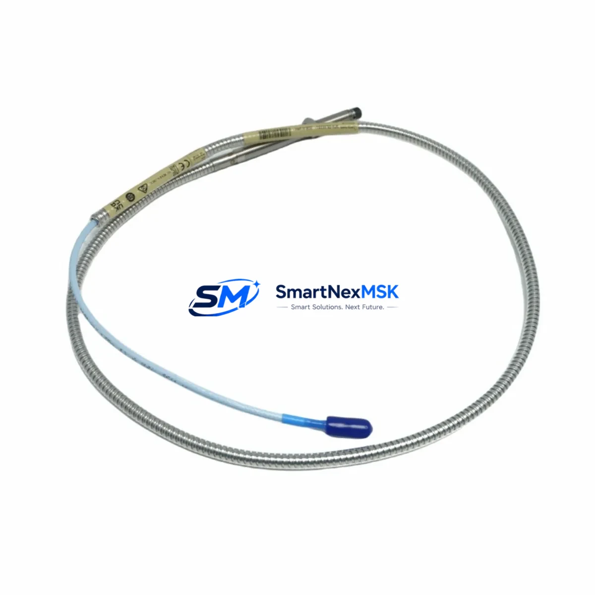
The Bently Nevada 330103-00-06-10-12-05 is an 8mm proximity transducer engineered for the 3300 XL Series continuous vibration monitoring system. In rotating machinery protection applications — turbines, compressors, pumps, and gearboxes — this transducer serves as the primary sensing element for shaft displacement and radial vibration measurement. When this component fails or degrades, the entire machinery protection loop is compromised, creating an unacceptable risk of undetected mechanical fault escalation and unplanned shutdown.
Maintaining a certified spare of the 330103-00-06-10-12-05 in your on-site inventory is a fundamental element of any proactive maintenance strategy. Maintenance engineers and procurement teams operating critical rotating equipment cannot afford lead times measured in weeks when a transducer failure triggers a machinery trip. This listing provides an original, tested, and warranty-backed replacement unit ready for immediate deployment.
Spare Maintenance Table
| Parameter | Specification |
|---|---|
| Part Number / SKU | 330103-00-06-10-12-05 |
| Brand | Bently Nevada |
| Series | 3300 XL |
| Type | 8mm Proximity Transducer (Eddy-Current) |
| Probe Diameter | 8 mm |
| Cable Length | 6 m (integral cable) |
| Extension Cable | Compatible with 330130 Series extension cables |
| Driver / Oscillator | Compatible with 3300 XL Proximitor® Sensor (e.g., 330180) |
| Measurement Range | 0.25 mm – 2.25 mm (linear range) |
| Output Sensitivity | 7.87 V/mm (200 mV/mil) |
| Supply Voltage | –24 VDC (nominal) |
| Operating Temperature | –35°C to +177°C (probe tip) |
| Target Material | AISI 4140 steel or equivalent ferromagnetic alloy |
| Installation | M10 x 1 thread, locknut included |
| Application Environment | Turbines, compressors, pumps, gearboxes, motors |
| Compatibility | 3300 XL monitoring system; API 670 compliant installations |
| Origin | USA |
| Condition | Original spare, factory-tested |
| Warranty | 12 Months |
Maintenance Planning for Continuous Operation
Replacing the 330103-00-06-10-12-05 transducer in the field is rarely an isolated task. A thorough maintenance engineer will treat a transducer replacement as an opportunity to inspect and verify the integrity of the entire vibration monitoring loop and associated control cabinet components. Failure to do so risks a repeat trip event caused by an adjacent degraded component.
When replacing this proximity transducer, the following components should be inspected or replaced as part of the same maintenance window:
- 330130 Series Extension Cable: The integral cable on the 330103 probe connects to the Proximitor® via a 330130 extension cable. Inspect for jacket cracking, connector corrosion, and continuity. A degraded extension cable will introduce gap voltage errors indistinguishable from a failing probe.
- 330180 Proximitor® Sensor (3300 XL Driver): The oscillator-demodulator unit that powers the probe and converts gap distance to a –24 VDC proportional output. Verify output voltage linearity across the full measurement range after probe replacement.
- 3300/16 or 3500/42 Monitor Module: The rack-mounted monitor card that processes the Proximitor® output. Check channel configuration, alert/danger setpoints, and OK relay status after transducer swap.
- –24 VDC Power Supply Module: The dedicated DC power supply feeding the Proximitor® sensor. Measure output voltage under load; a sagging supply will cause false OK relay dropout and nuisance trips.
- Terminal Blocks and Field Wiring: Inspect all screw terminals in the junction box and control cabinet for corrosion, loose connections, and correct wire labeling. Vibration environments accelerate terminal loosening.
- Barrier or Zener Barrier (IS Installations): In intrinsically safe installations, verify the associated Zener barrier or galvanic isolator is within calibration and has not been damaged by a fault event.
- OK Relay and Trip Relay Outputs: Test the OK relay output continuity and the danger relay trip function using the monitor’s built-in test capability or a relay tester.
- Signal Cable Shielding and Grounding: Confirm single-point grounding of the coaxial cable shield. Multiple ground points introduce noise that can mask real vibration signals or trigger false alarms.
- Keyphasor® Transducer (if installed): If the machine uses a Keyphasor® probe (e.g., 330980 Series) for phase reference, inspect it simultaneously — Keyphasor® and radial probes share the same environmental exposure and maintenance interval.
- Rack Backplane and I/O Connectors: In 3500 Series rack installations, inspect the backplane connectors for bent pins and oxidation, particularly if the rack has been in service for more than five years.
Procurement engineers should note that the 330103-00-06-10-12-05 is a system-matched component. Substituting a non-matched probe body, extension cable, or Proximitor® from a different calibration set will invalidate the system calibration and may not meet API 670 accuracy requirements. Always procure the probe, extension cable, and Proximitor® as a matched set when replacing a complete channel.
Site Replacement Workflow
The following workflow is recommended for maintenance teams replacing the 330103-00-06-10-12-05 in a live industrial facility:
- Obtain Work Permit: Coordinate with operations for a machinery isolation or reduced-speed window. Confirm the monitor channel is in bypass mode to prevent a spurious trip during probe removal.
- Document As-Found Gap Voltage: Record the existing gap voltage (target: –10.0 VDC ± 0.5 VDC at nominal gap) before disconnecting the old probe. This establishes a baseline for comparison with the new unit.
- Remove Old Transducer: Disconnect the extension cable at the junction box. Unscrew the probe from the bracket using the correct spanner. Inspect the probe tip for wear, pitting, or contamination from shaft contact.
- Install Replacement Unit: Thread the new 330103-00-06-10-12-05 into the bracket. Set the gap to the manufacturer-specified nominal distance (typically 1.0 mm for 8mm probes on steel targets) using a feeler gauge or gap voltage measurement.
- Verify Gap Voltage: With the Proximitor® powered, confirm gap voltage is within the linear range (–10.0 VDC ± 0.5 VDC). Adjust gap as required and secure the locknut.
- Functional Test: Remove the channel from bypass. Observe the OK relay status and confirm the vibration reading is within expected baseline levels for the machine at current operating speed.
- Update Maintenance Records: Log the replacement date, as-found gap voltage, as-left gap voltage, and new unit serial number in the CMMS. Schedule the next inspection interval per your predictive maintenance program.
This workflow minimizes downtime exposure and ensures the replacement is fully verified before the machine is returned to normal operation. Units supplied through this listing are pre-tested prior to shipment, reducing the risk of installing a defective spare.
Spare Parts Support FAQ
Q1: Is the 330103-00-06-10-12-05 compatible with both the 3300 XL and the older 3300 Series monitors?
The 330103-00-06-10-12-05 is specifically calibrated for the 3300 XL Proximitor® system. While the physical probe body is similar to earlier 3300 Series probes, the calibration coefficients differ. Using this probe with a non-XL Proximitor® will result in a calibration error. Always confirm the Proximitor® model number before ordering. If you are operating a legacy 3300 (non-XL) system, contact us to identify the correct matched probe part number.
Q2: What is included in the 12-month warranty, and what does it cover?
All units are covered by a 12-month warranty from the date of shipment. The warranty covers manufacturing defects, electrical failure under normal operating conditions, and out-of-specification performance verified by calibration test. It does not cover damage resulting from incorrect installation, shaft contact, chemical contamination, or operation outside the specified temperature and voltage range. Warranty claims are processed with a replacement unit dispatched upon receipt and inspection of the returned part.
Q3: How do you verify the unit before shipment?
Each 330103-00-06-10-12-05 unit undergoes pre-shipment functional testing including gap voltage linearity verification across the full measurement range, OK relay output confirmation, and cable continuity check. A test report is available upon request. Units are packaged in anti-static, shock-protected packaging suitable for international air freight.
Q4: Can you supply the complete 3300 XL channel kit — probe, extension cable, and Proximitor® — as a matched set?
Yes. We maintain stock of matched 3300 XL channel components including 330103 Series probes, 330130 Series extension cables, and 330180 Proximitor® sensors. Ordering a matched set ensures calibration traceability and simplifies site installation. Contact our technical sales team with your machine tag number and existing channel configuration for a matched set quotation.
© 2026 SMARTNEXMSK. All rights reserved.
Original Source: https://smartnexmsk.com
Contact: sales@smartnexmsk.com | +86 18259474341


