Bently Nevada 330103-00-06-15-02-05 Retrofit-Ready 8mm Proximity Transducer for 3300 XL Control Systems
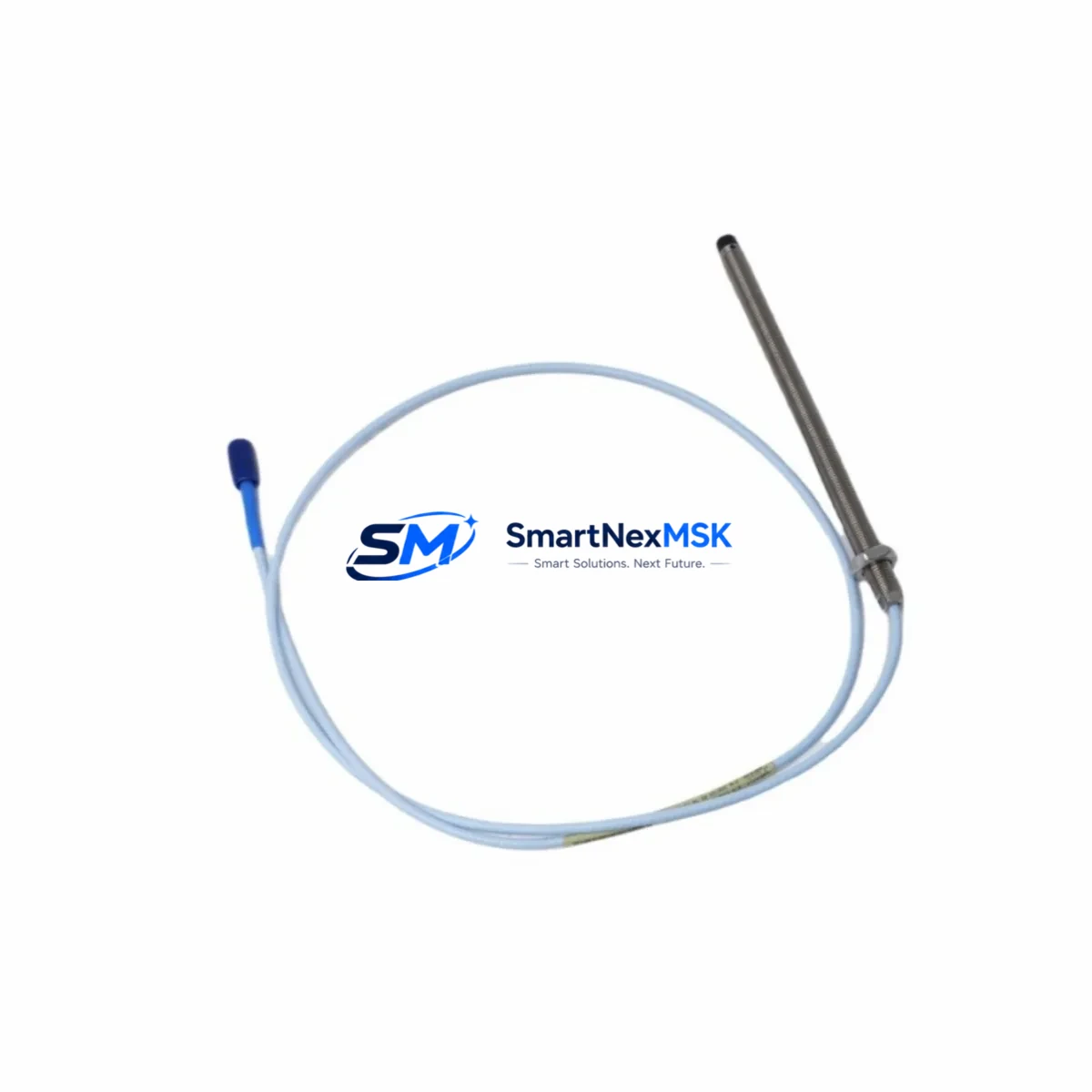
The Bently Nevada 330103-00-06-15-02-05 is an 8mm eddy-current proximity transducer engineered for the 3300 XL Series vibration monitoring platform. As legacy rotating machinery protection systems age and OEM support windows close, this transducer serves as a direct retrofit replacement for facilities managing turbines, compressors, pumps, and gearboxes that rely on continuous shaft displacement and vibration data. Whether you are replacing a failed unit, upgrading a deteriorating cable assembly, or standardizing spare parts inventory across multiple train protection panels, the 330103-00-06-15-02-05 delivers the dimensional accuracy, sensitivity, and signal linearity required for uninterrupted machinery protection.
This transducer is designed to interface directly with the 3300 XL proximitor/sensor system. The 8mm tip diameter and standard 5-metre integral cable configuration ensure compatibility with existing conduit runs and junction box terminations without requiring re-routing or additional cable extensions. The output sensitivity of 7.87 V/mm (200 mV/mil) aligns with the input specifications of the 3300 XL proximitor, eliminating the need for signal conditioning adjustments during commissioning. Engineers replacing the earlier 330103-00-06-10-02-05 (5-metre) or transitioning from the 7200 Series transducer system will find the electrical and mechanical interface largely compatible, though gap voltage recalibration at the proximitor is always recommended after any transducer swap.
Upgrade Compatibility Table
| Parameter | 330103-00-06-15-02-05 | Notes / Retrofit Guidance |
|---|---|---|
| Tip Diameter | 8 mm | Matches standard 3300 XL mounting boss; no adapter required |
| Cable Length | 5 m (integral) | Verify conduit run length before installation; extension cables available separately |
| Output Sensitivity | 7.87 V/mm (200 mV/mil) | Matches 3300 XL Proximitor input; no signal conditioning change needed |
| Supply Voltage | −24 VDC (nominal) | Confirm proximitor power supply rail; 3300 XL power supply module must be verified |
| Linear Range | 0.25 – 2.54 mm (10 – 100 mil) | Set gap to midpoint ~1.0 mm (40 mil) during installation |
| Communication Compatibility | Analog (4–20 mA / voltage output via proximitor) | Compatible with DCS analog input cards and 3500 Series rack I/O modules |
| Mounting Thread | M10 × 1.0 | Standard 3300 XL bracket; no re-machining required |
| Replacement Recommendation | Direct drop-in for 330103-00-06-15-02-05 | Also replaces 330103-00-06-10-02-05 with cable length verification |
| Commissioning Focus | Gap voltage, polarity, and proximitor output scaling | Use Bently Nevada field calibration procedure; verify OK/NOT OK relay setpoints |
| Warranty | 12 Months | Covers manufacturing defects; includes pre-shipment functional test report |
Retrofit Planning for Existing Automation Systems
Successful retrofit of the 330103-00-06-15-02-05 into an operating plant environment requires systematic planning across mechanical, electrical, and software domains. Before removing the failed transducer, document the existing gap voltage reading at the 3300 XL proximitor output terminal — typically displayed on the front panel of the 3500/42M Proximitor I/O Module or readable via the System 1 condition monitoring software. This baseline reading confirms the shaft-to-probe gap and provides a reference for post-installation verification.
On the electrical side, confirm that the −24 VDC power supply feeding the proximitor is within specification. The 3300 XL power supply module (such as the 3300/20 or 3300/25 power supply) must deliver stable voltage under load; a degraded power supply is a common root cause of transducer false trips that is often misdiagnosed as a transducer failure. Inspect the terminal block connections at the proximitor junction box — corroded or loose terminals on the COM, PWR, and OUT conductors are a frequent source of signal noise that will persist even after a new transducer is installed.
For facilities running a 3500 Series rack-based protection system alongside the 3300 XL field transducers, verify that the 3500/42M or 3500/40M Proximitor I/O Module firmware is current and that the channel configuration in the 3500 Rack Configuration Software reflects the correct transducer type and gap voltage limits. If the plant is also managing a parallel DCS integration — for example, feeding vibration data to a Honeywell Experion or Emerson DeltaV system via the 3500 Gateway Module — confirm that the analog output scaling at the I/O module matches the DCS input card range before returning the channel to service.
Cable routing deserves particular attention in high-temperature or high-vibration environments. The integral cable of the 330103-00-06-15-02-05 is rated for continuous operation in demanding industrial conditions, but the extension cable — if a 330130-080-00-00 or similar armoured extension is used to bridge the distance between the transducer and the proximitor — must be inspected for jacket integrity, shield continuity, and connector seating. A compromised shield on the extension cable will introduce electrical noise that degrades the signal quality at the proximitor, leading to erratic vibration readings and nuisance trips.
For plants managing a broader machinery protection upgrade, the 330103-00-06-15-02-05 is frequently deployed alongside the 330180-X1-05 proximity transducer (used for axial position measurement on the same shaft), the 330500-02-05 velocity transducer (for seismic/casing vibration), and the 3300 XL 8mm Proximitor (330130-040-01-00) as the signal conditioning unit. Facilities upgrading from the older 7200 Series to the 3300 XL platform will also need to address the 7200/60-XX-XX proximitor replacement and verify that the new transducer’s sensitivity curve is correctly entered into the protection system channel configuration.
Downtime Control During System Migration
Minimising unplanned downtime during a proximity transducer replacement is achievable with disciplined pre-work. The most effective approach is to pre-configure and bench-test the replacement 330103-00-06-15-02-05 before the maintenance window opens. Using a Bently Nevada field calibration fixture or a precision gap simulator, verify the transducer’s output voltage at the nominal gap (typically 1.0 mm / 40 mil) and confirm it falls within the ±0.5% tolerance band specified for the 3300 XL system. Document the as-found and as-left gap voltages on the maintenance record.
During the swap, place the affected protection channel in bypass mode via the 3500 Rack Configuration Software or the local bypass switch on the 3500/20 Rack Interface Module before disconnecting the transducer. This prevents a spurious NOT OK condition from triggering a machinery trip or DCS alarm during the physical replacement. Maintain the bypass for the minimum time necessary — record the bypass start and end times in the plant’s safety management system.
After reinstalling the 330103-00-06-15-02-05 and reconnecting the extension cable, allow the proximitor a 30-second warm-up period before reading the gap voltage. Adjust the transducer axial position using the locknut and jam nut on the mounting bracket until the gap voltage matches the pre-removal baseline. Remove the channel bypass, confirm the OK relay energises, and verify that the vibration reading on the System 1 or DCS display is stable and consistent with adjacent channels on the same shaft. A final functional test — including a simulated high-vibration condition using a calibrated signal injector — is recommended before returning the machine to service.
For facilities managing multiple simultaneous transducer replacements across a train, stagger the bypass windows to ensure that no more than one protection channel per shaft is in bypass at any time. This preserves the integrity of the overall machinery protection strategy and satisfies most plant safety management requirements without requiring a full machine shutdown.
Retrofit Support FAQ
Q1: Is the 330103-00-06-15-02-05 a direct replacement for the 330103-00-06-10-02-05?
A: The two part numbers differ only in cable length (5 m vs. the shorter variant). The tip diameter, thread pitch, sensitivity, and supply voltage are identical. If your existing conduit run accommodates the 5-metre cable, the 330103-00-06-15-02-05 is a direct drop-in replacement. If the original installation used a shorter cable with a separate extension, verify that the total cable length (transducer + extension) does not exceed the proximitor’s maximum recommended cable length, typically 9 m for the 3300 XL system.
Q2: Do I need to recalibrate the 3300 XL proximitor after installing this transducer?
A: Yes. Even when replacing a like-for-like part number, gap voltage recalibration at the proximitor is always recommended. Mechanical tolerances in the mounting bracket and shaft surface condition mean that the as-installed gap will differ slightly from the previous installation. Use the proximitor’s front-panel gap voltage indicator or the System 1 software to set the gap to the midpoint of the linear range (approximately 1.0 mm / 40 mil) and confirm the output is within specification before removing the channel bypass.
Q3: What pre-shipment testing is performed on this transducer?
A: Each 330103-00-06-15-02-05 unit supplied by SMARTNEXMSK undergoes a functional output test at nominal gap and supply voltage, cable continuity and shield integrity verification, and dimensional inspection of the tip and thread. A test report is available upon request. All units are covered by a 12-month warranty against manufacturing defects from the date of shipment.
Q4: Can this transducer be used with a 3500 Series rack system instead of the 3300 XL?
A: Yes, provided the 3500 rack is fitted with a compatible Proximitor I/O Module (such as the 3500/42M) configured for 8mm transducer input. The 330103-00-06-15-02-05 sensitivity and supply voltage are compatible with the 3500 Series proximitor channel specifications. Confirm the channel configuration in the 3500 Rack Configuration Software reflects the correct transducer model and gap voltage limits before commissioning.
© 2026 SMARTNEXMSK. All rights reserved.
Original Source: https://smartnexmsk.com
Contact: sales@smartnexmsk.com | +86 18259474341


