Bently Nevada 330103-00-06-20-02-00 Retrofit-Ready Proximity Transducer for 3300 XL Control Systems
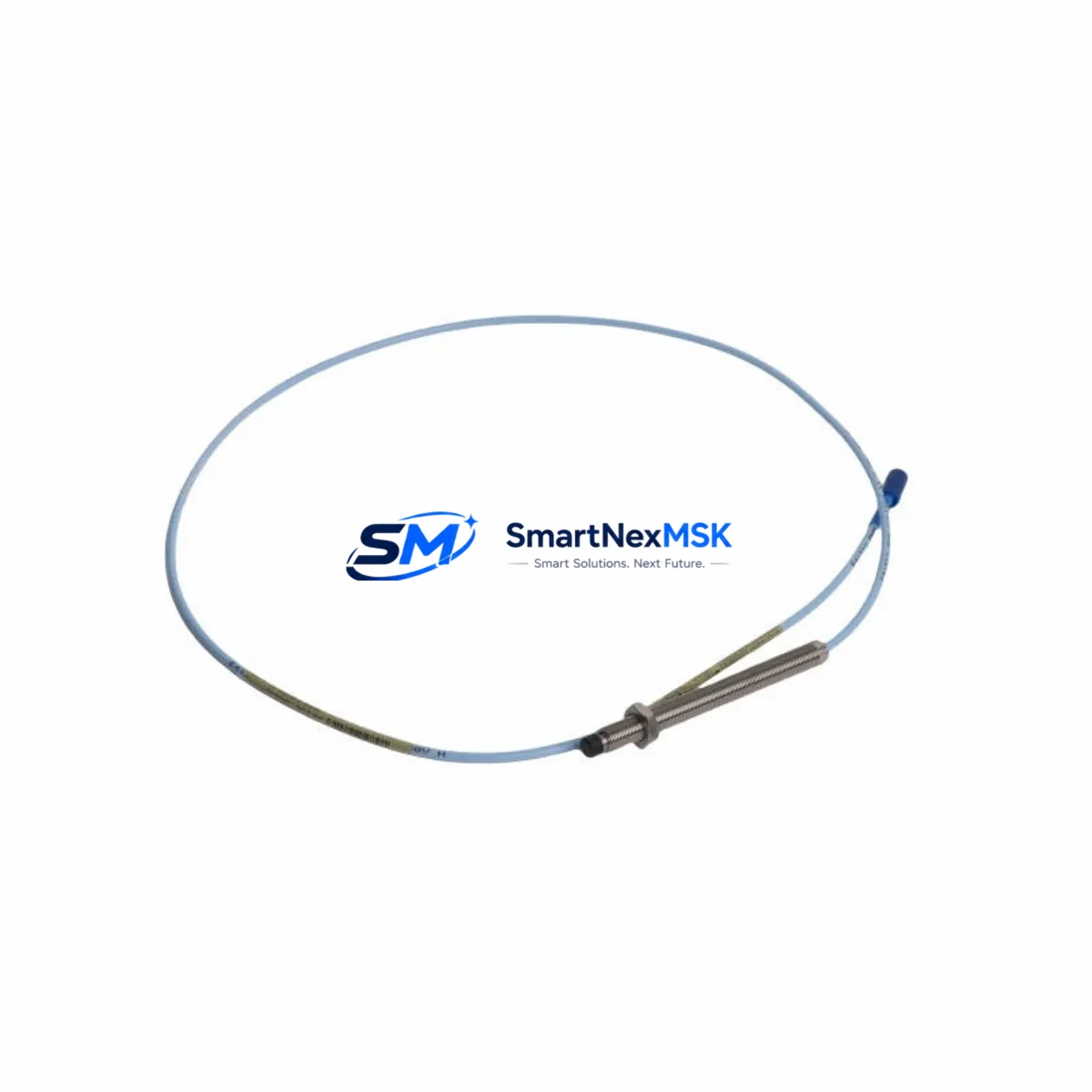
The Bently Nevada 330103-00-06-20-02-00 is a 3300 XL Series eddy-current proximity transducer engineered for continuous vibration and position monitoring in rotating machinery applications. As legacy 3300 Series installations reach end-of-service milestones, this transducer serves as the primary retrofit and drop-in replacement solution for facilities upgrading from discontinued 3300 standard-series sensors to the 3300 XL platform — without requiring full rack replacement or reprogramming of existing System 1 condition monitoring software.
This transducer operates on the standard Bently Nevada two-wire eddy-current principle, producing a DC voltage output proportional to the gap between the probe tip and the observed target surface. It is fully compatible with the 3300 XL 8mm Extension Cable assemblies and the 3300 XL Proximitor® Sensor (driver), making it a direct mechanical and electrical substitute in most existing installations. Engineers replacing worn or failed sensors in turbine, compressor, pump, and motor monitoring panels will find the 330103-00-06-20-02-00 ready for immediate installation with minimal field calibration.
Upgrade Compatibility Table
| Parameter | 330103-00-06-20-02-00 (3300 XL) | Legacy 3300 Standard Series |
|---|---|---|
| Probe Diameter | 8 mm | 8 mm |
| Cable Length | 2.0 m (integral) | 2.0 m (integral) |
| Extension Cable | 3300 XL 8mm Extension Cable | 3300 Standard Extension Cable |
| Proximitor® Driver | 3300 XL Proximitor® Sensor | 3300 Standard Proximitor® |
| Output Range | −18 VDC nominal | −18 VDC nominal |
| Linear Range | 0.25 mm – 2.26 mm | 0.25 mm – 2.26 mm |
| Temperature Rating | −35°C to +177°C | −35°C to +160°C |
| Installation | Direct drop-in; verify thread engagement | N/A (being replaced) |
| Communication Compatibility | System 1 Evolution, System 1 Classic | System 1 Classic |
| Replacement Recommendation | Recommended for all 3300 Standard retrofits | Discontinue; replace with 3300 XL |
| Commissioning Focus | Gap voltage verification, scale factor check | — |
| Warranty | 12 Months | — |
Retrofit Planning for Existing Automation Systems
Successful integration of the 330103-00-06-20-02-00 into an existing monitoring rack begins with a thorough review of the installed 3300 XL Proximitor® Sensor driver module. Confirm that the driver accepts the 3300 XL 8mm probe family and that the extension cable — typically a 3300 XL 5m or 9m extension — is in serviceable condition before committing to a probe-only swap. In many retrofit scenarios, the extension cable and Proximitor® driver are replaced simultaneously to eliminate latent wiring faults that could mask the new probe’s performance.
For installations housed in a 3500 Series monitoring rack, verify that the 3500/42M Proximitor®/Seismic Monitor or 3500/40M Proximitor® Monitor card is configured for the correct transducer type and gap voltage range. The 3500 rack’s I/O module terminal assignments must match the field wiring from the junction box to the Proximitor® driver. Technicians should also confirm that the Keyphasor® transducer — often a 330180 or 330130 series probe — remains correctly gapped and phased after any adjacent probe replacement, as Keyphasor signal integrity directly affects vibration vector calculations in System 1.
Where the retrofit involves migrating from a standalone 3300 monitoring panel to a fully integrated 3500 Series rack, additional planning is required for the 3500/20 Power Supply Module capacity. Each Proximitor® driver draws supply current from the rack backplane; adding channels during an upgrade must remain within the power budget of the installed 3500/20 or 3500/15 power supply. Document all terminal block wiring at the field junction box before disconnection, and photograph the existing cable routing to preserve the original installation reference.
In control cabinets where the 330103-00-06-20-02-00 is being installed alongside new I/O expansion — such as adding a 3500/64M Process Variable Monitor for temperature or pressure inputs — coordinate the rack slot assignment with the existing channel map to avoid address conflicts in the System 1 database. If the plant uses a DCS interface via the 3500 Gateway or a Modbus/TCP link to a third-party SCADA, update the tag mapping table to reflect any channel renumbering introduced during the retrofit.
All replacement probes should be bench-tested prior to installation using a calibrated gap simulator to verify the scale factor (nominally 7.87 V/mm for 8mm probes) and confirm the output voltage at the standard 1.0 mm gap. This pre-installation check, combined with a final in-situ gap voltage measurement after mounting, ensures the 330103-00-06-20-02-00 meets the plant’s acceptance criteria before the machine is returned to service.
Downtime Control During System Migration
Minimizing unplanned downtime during a proximity transducer retrofit requires a structured hot-swap or planned-outage strategy. Where the process permits a brief controlled shutdown, the preferred approach is to bypass the affected monitoring channel in System 1 — placing it in bypass mode rather than deleting the point — so that the existing alarm setpoints, trend history, and vector reference data are preserved. Once the 330103-00-06-20-02-00 is installed and gapped, the channel is re-enabled and the gap voltage is verified against the original baseline before the bypass is lifted.
For critical machinery where even a brief outage is unacceptable, a parallel monitoring strategy using a temporary portable data collector can maintain vibration surveillance while the permanent transducer is replaced. This approach is particularly valuable in compressor trains or steam turbines where the 3500 rack’s OK relay output is wired into the machine’s protective shutdown logic. Confirm with the control room that the OK relay bypass is active and documented in the permit-to-work system before disconnecting any field wiring.
After reinstallation, perform a full channel check: verify the DC gap voltage, confirm the AC dynamic response using a known vibration source or bump test, and validate the Keyphasor® once-per-revolution marker in System 1 before releasing the machine to operations. Retain the replaced 330103-00-06-20-02-00 unit for the 12-month warranty period as a reference in the event of any post-installation performance query.
Retrofit Support FAQ
Q1: Is the 330103-00-06-20-02-00 a direct replacement for the legacy 3300 standard 8mm proximity probe?
Yes. The 330103-00-06-20-02-00 is mechanically and electrically compatible with existing 8mm probe installations. However, it must be paired with a 3300 XL Proximitor® Sensor driver and 3300 XL extension cable. If the existing driver is a standard 3300 Proximitor®, the driver must also be upgraded to complete the retrofit.
Q2: What wiring changes are required at the terminal block during installation?
In most cases, no wiring changes are required at the field junction box if the existing cable is a 3300 XL extension. Verify polarity and shield grounding at the Proximitor® driver terminal block. If replacing both the probe and extension cable, re-terminate the new cable using the original wiring diagram and confirm continuity before powering the driver.
Q3: How is compatibility with System 1 Evolution verified after replacement?
After installation, open the System 1 channel configuration for the replaced point and confirm the transducer type, scale factor, and gap voltage setpoints match the 330103-00-06-20-02-00 specification. Run a live gap voltage check and compare against the pre-replacement baseline. No software license changes are required for a like-for-like probe replacement within the same 3300 XL family.
Q4: What does the 12-month warranty cover, and how is a claim initiated?
The 12-month warranty covers manufacturing defects and premature failure under normal operating conditions. Each unit shipped by SMARTNEXMSK is tested prior to dispatch. To initiate a warranty claim, contact sales@smartnexmsk.com with the order reference, installation date, and a description of the observed fault. Replacement units are dispatched upon confirmation of the defect.
© 2026 SMARTNEXMSK. All rights reserved.
Original Source: https://smartnexmsk.com
Contact: sales@smartnexmsk.com | +86 18259474341


