Bently Nevada 330103-00-07-15-02-00 Spare 3300 XL: Precision Spare for Vibration Monitoring Downtime Control
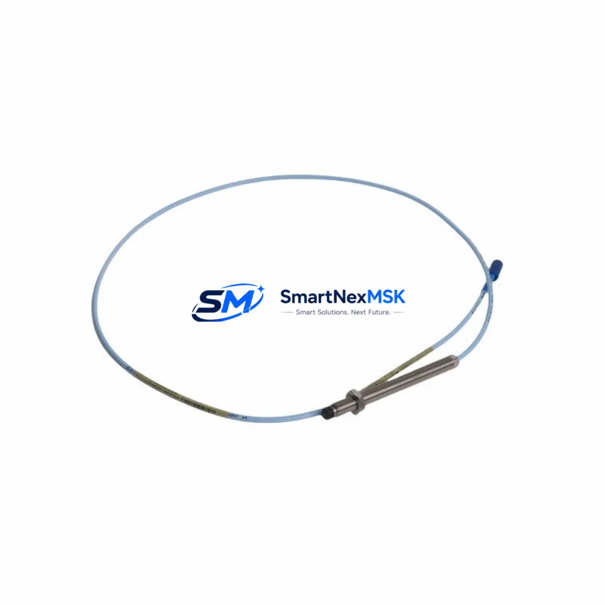
The Bently Nevada 330103-00-07-15-02-00 is an original 8mm eddy current proximity transducer engineered for the 3300 XL Series continuous vibration monitoring system. In rotating machinery protection — turbines, compressors, pumps, and gearboxes — this transducer is the primary sensing element for shaft radial vibration, axial position, and differential expansion measurement. When this component fails or degrades, the entire protection loop is compromised, exposing critical assets to undetected mechanical faults and potential catastrophic failure. Maintaining a verified spare on the shelf is not optional; it is a fundamental requirement of any serious predictive maintenance program.
For maintenance engineers managing aging DCS or PLC-integrated machinery protection systems, the 330103-00-07-15-02-00 represents a direct, drop-in replacement that preserves calibration traceability and system compatibility without requiring reconfiguration of the 3300 XL monitor rack. For procurement engineers, sourcing this part from a reliable supplier with documented testing and a 12-month warranty eliminates the risk of counterfeit components entering the protection loop — a risk that carries both safety and regulatory consequences.
Spare Maintenance Table
| Parameter | Specification |
|---|---|
| Part Number | 330103-00-07-15-02-00 |
| Brand | Bently Nevada |
| Series | 3300 XL |
| Type | 8mm Eddy Current Proximity Transducer |
| Measurement | Radial Vibration, Axial Position, Differential Expansion |
| Sensitivity | 7.87 V/mm (200 mV/mil) |
| Linear Range | 0.25 mm – 2.25 mm (10 – 90 mil) |
| Operating Temperature | -35°C to +120°C |
| Cable Length | 5m (standard; specify at order) |
| Connector | 3-pin MIL-C-5015 compatible |
| Compatibility | 3300 XL Monitor, 3500 Series (with adapter), Proximitor® 3300 XL |
| Installation | Threaded tip, 3/8-24 UNF mounting |
| Application Environment | Turbines, Compressors, Pumps, Gearboxes, Fans |
| Origin | USA |
| Condition | Original, New / Refurbished-Tested |
| Warranty | 12 Months |
| Pre-shipment Test | Sensitivity, linearity, and insulation resistance verified |
Maintenance Planning for Continuous Operation
Replacing the 330103-00-07-15-02-00 transducer in the field is rarely an isolated task. A disciplined maintenance engineer will treat this replacement as an opportunity to inspect the entire vibration monitoring loop and adjacent control cabinet components. The Proximitor® 3300 XL signal conditioner — typically mounted in the monitor rack — should be checked for output voltage drift and connector corrosion before the new transducer is commissioned. If the Proximitor shows signs of aging, replacing it concurrently with the transducer eliminates a second unplanned outage within weeks.
The extension cable (3300 XL series, 330130-xx-xx) connecting the transducer to the Proximitor is a frequent source of intermittent faults due to mechanical abrasion, connector oxidation, or oil ingress. Inspect the full cable run and replace if the outer jacket shows cracking or if continuity tests reveal resistance above specification. Similarly, the armored conduit and cable gland fittings at the machinery casing penetration point should be verified for integrity.
At the monitor rack level, the 3300/16-xx-xx monitor module receives the Proximitor output and converts it to a 4–20 mA or relay trip signal for the DCS or safety PLC. Verify that the monitor’s OK relay is functioning and that the trip setpoints have not drifted. If the plant uses a 3500 Series rack for integration, confirm that the 3500/42M or 3500/44M monitor card firmware is compatible with the transducer sensitivity range.
Power supply integrity is critical. The 3300 XL Proximitor requires a regulated –24 VDC supply, typically sourced from a dedicated instrument power supply module within the control cabinet. Measure supply voltage at the Proximitor terminal under load; values outside –22 to –26 VDC will cause measurement errors. Redundant power supply modules should be tested for automatic switchover. Terminal blocks (Phoenix Contact or equivalent) at the Proximitor power and signal terminals should be inspected for loose connections and re-torqued to specification.
For plants running integrated machinery protection with a DCS such as Emerson DeltaV or Honeywell Experion, verify that the analog input card receiving the vibration signal is reading correctly after transducer replacement. Signal isolators or barriers in the loop — particularly in hazardous area installations — should be tested for correct output scaling. Zener barriers or galvanic isolators protecting the intrinsically safe circuit must be within their rated voltage and current limits.
Finally, update the CMMS (Computerized Maintenance Management System) record for this asset with the new transducer serial number, installation date, and gap voltage reading at commissioning. A correctly set gap voltage (typically –10.0 VDC ± 0.5 VDC for this transducer at the center of the linear range) is the primary commissioning verification step and should be documented for future reference.
Site Replacement Workflow
Step 1 — Isolation and Permit: Obtain a hot-work or cold-work permit as applicable. Isolate the monitor channel at the 3300 XL monitor rack by placing the channel in bypass mode to prevent a spurious trip during replacement. Do not de-energize the Proximitor until the channel is confirmed in bypass.
Step 2 — Gap Measurement Before Removal: Record the existing gap voltage displayed on the monitor or measured at the Proximitor output terminals. This baseline confirms whether the old transducer was within range or had already drifted, and provides a reference for the new installation.
Step 3 — Transducer Removal: Disconnect the extension cable at the transducer connector. Using the correct spanner, unscrew the transducer from the mounting bracket. Note the number of turns required to reach the recorded gap voltage — this provides a starting point for the new transducer installation.
Step 4 — New Transducer Installation: Thread the 330103-00-07-15-02-00 into the mounting bracket. Adjust the gap to achieve the target gap voltage (–10.0 VDC ± 0.5 VDC). Lock the locknut securely. Reconnect the extension cable and verify connector seating.
Step 5 — Commissioning Verification: Remove the channel from bypass at the monitor rack. Confirm the OK LED is illuminated and the gap voltage is within specification on the monitor display. Verify that the vibration reading is stable and consistent with adjacent channels or historical baseline values.
Step 6 — Documentation: Record the new transducer part number, serial number, gap voltage, and installation date in the CMMS. Retain the removed transducer for failure analysis if the replacement was unplanned.
This workflow minimizes machine downtime to the duration of the physical replacement — typically 30 to 90 minutes for an experienced technician — and ensures the protection system is returned to full operational status with documented traceability.
Spare Parts Support FAQ
Q1: What is the recommended spare parts strategy for the 330103-00-07-15-02-00 in a critical rotating machinery application?
For any machine classified as critical (no installed spare, production impact if offline), maintain a minimum of one transducer per monitored measurement point in the on-site spare parts inventory. For plants with multiple identical machines, a pooled inventory of two to three units per transducer type is typically sufficient. Pair each transducer spare with a matching extension cable and a Proximitor® 3300 XL unit to ensure the complete measurement chain can be restored without waiting for procurement.
Q2: How is the 330103-00-07-15-02-00 verified before shipment?
Each unit supplied by SMARTNEXMSK undergoes pre-shipment testing covering sensitivity verification (7.87 V/mm ± 5%), linearity across the full measurement range, insulation resistance between the coil and shield, and connector integrity. A test report is available upon request. Units are packaged in anti-static, shock-protected packaging to prevent transit damage.
Q3: Is the 330103-00-07-15-02-00 compatible with the Bently Nevada 3500 Series monitoring system?
The 330103-00-07-15-02-00 is natively designed for the 3300 XL Series. Compatibility with the 3500 Series depends on the specific monitor card and Proximitor configuration. In many installations, the 3300 XL transducer and Proximitor combination can interface with 3500 Series monitor cards that accept a –24 VDC Proximitor input. Confirm the monitor card model and input specification before ordering. SMARTNEXMSK technical support can assist with compatibility verification.
Q4: What does the 12-month warranty cover, and what is the claims process?
The 12-month warranty covers manufacturing defects, premature failure under normal operating conditions, and out-of-specification performance verified by test. It does not cover damage resulting from incorrect installation, overvoltage, mechanical impact, or operation outside the rated temperature range. To initiate a warranty claim, contact SMARTNEXMSK with the order number, installation date, failure description, and gap voltage readings at installation and at failure. Replacement units are dispatched within 3 business days of claim approval.
© 2026 SMARTNEXMSK. All rights reserved.
Original Source: https://smartnexmsk.com
Contact: sales@smartnexmsk.com | +86 18259474341


