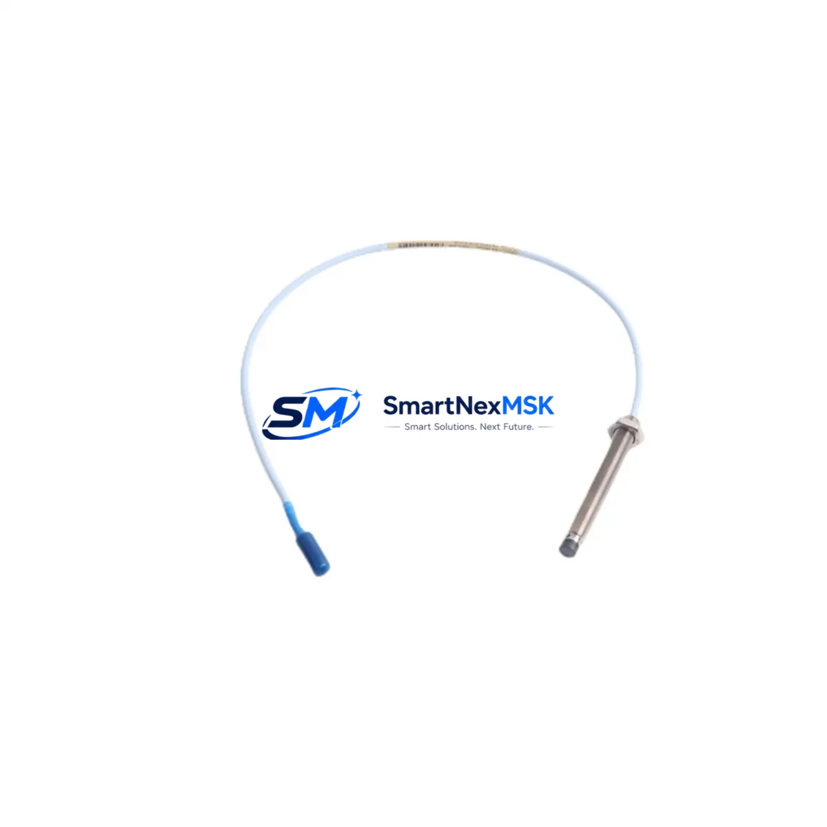
Bently Nevada 330103-00-08-05-02-00 Retrofit-Ready Proximity Transducer for 3300 XL Control Systems
The Bently Nevada 330103-00-08-05-02-00 is an 8mm proximity transducer engineered for seamless integration into legacy 3300 XL vibration monitoring systems. As original Bently Nevada hardware reaches end-of-life or becomes increasingly difficult to source through OEM channels, this retrofit-ready replacement provides a verified drop-in solution for facilities managing rotating machinery protection, shaft vibration measurement, and radial position monitoring across turbines, compressors, pumps, and gearboxes.
This transducer operates within the standard Bently Nevada eddy-current sensing architecture, maintaining full signal compatibility with the 3300 XL proximitor/seismic monitor series. Engineers undertaking control system modernization projects can deploy this unit without modifying existing cable runs, terminal blocks, or monitor rack configurations — a critical advantage when minimizing planned outage windows.
Upgrade Compatibility Table
| Parameter | Specification / Compatibility Note |
|---|---|
| SKU / Part Number | 330103-00-08-05-02-00 |
| Brand | Bently Nevada |
| Series | 3300 XL |
| Sensor Type | 8mm Eddy-Current Proximity Transducer |
| Cable Length | 5m (standard; extension cables available) |
| Output Signal | -18 VDC nominal (compatible with 3300 XL proximitor input) |
| Thread / Mounting | M10 x 1 standard thread; direct retrofit to existing brackets |
| Connector Interface | Standard coaxial connector; mates with 330130 extension cable |
| Monitor Compatibility | 3300/16 Dual Voting, 3300/20 Radial Vibration, 3300/25 Thrust Position |
| Communication Protocol | Analog 4–20 mA / voltage output; compatible with existing DCS/PLC analog input modules |
| Replacement For | 330103-00-08-05-02-00 (OEM), legacy 330103 series variants |
| Installation Requirement | Gap voltage calibration required post-installation (typically –10.0 VDC ±0.5 V at nominal gap) |
| Debugging Focus | Gap setting, signal linearity check, OK relay status verification on monitor card |
| Warranty | 12 Months from date of shipment |
Retrofit Planning for Existing Automation Systems
Successful deployment of the 330103-00-08-05-02-00 in a brownfield environment requires a structured pre-installation review. Begin by auditing the existing 3300 XL rack configuration: confirm the monitor card slot assignments, verify that the 3300/05 power supply module is delivering stable ±24 VDC to the proximitor, and document the current gap voltage readings for each installed transducer before removal. This baseline data is essential for post-installation comparison and acceptance testing.
When the existing 330103 transducer is removed, inspect the mounting boss for thread condition and clean the target area to remove any oxidation or debris that could affect the eddy-current field. Reinstall the 330103-00-08-05-02-00 to the same depth, then connect the 330130 extension cable — ensuring the coaxial connector is fully seated and the cable is routed away from high-voltage conductors to prevent electromagnetic interference on the signal line.
At the proximitor end, verify that the 3300 XL proximitor/seismic monitor (for example, a 3300/20 Radial Vibration Monitor or 3300/25 Thrust Position Monitor) is powered down before reconnecting the transducer cable. After reconnection, restore power and measure the gap voltage at the OK terminal. Adjust the transducer axial position until the gap voltage falls within the linear range specified in the system calibration record — typically –10.0 VDC ±0.5 V for an 8mm probe at nominal gap.
For facilities also upgrading their data acquisition layer, the analog output of the 3300 XL monitor integrates directly with standard PLC analog input modules and DCS field I/O cards. If the control platform is being migrated — for example, from a legacy Rockwell Automation 1756 ControlLogix analog input card to a newer 1756-IF16 module, or from a Honeywell C300 controller to a current-generation Experion PKS node — the 4–20 mA signal chain from the 330103-00-08-05-02-00 remains unchanged, simplifying the I/O mapping exercise. Similarly, if the HMI layer is being refreshed from a legacy FactoryTalk View SE display to a current Ignition SCADA screen, the vibration trend tags sourced from the 3300 XL monitor require only a tag address update rather than a signal reconfiguration.
Projects involving I/O expansion — such as adding a 3300/55 Keyphasor module to support phase-referenced vibration analysis, or integrating a 3300/46M Machinery Diagnostics Module for spectrum data — should be planned in parallel with the transducer replacement to avoid a second planned outage. Likewise, if the rack backplane or 3300 XL rack frame itself is being replaced due to corrosion or connector wear, coordinate the transducer swap within the same maintenance window to consolidate downtime.
Downtime Control During System Migration
Minimizing unplanned downtime is the primary operational concern when replacing proximity transducers on live rotating machinery protection systems. The recommended approach is a hot-standby swap strategy: where the machinery protection system supports dual-voting or redundant channel configurations — such as the 3300/16 Dual Voting Monitor — one channel can be placed in bypass mode while the transducer on the second channel is replaced and recalibrated, maintaining continuous protection coverage throughout the procedure.
Before any transducer is removed, export and archive the current monitor configuration from the System 1 condition monitoring software or equivalent historian platform. This preserves alarm setpoints, danger thresholds, and OK relay logic so that the replacement unit can be commissioned to identical parameters without relying on paper records. If the facility uses a Bently Nevada 3500 rack in parallel for critical machinery, cross-reference the 3500/42M Proximitor I/O Module channel assignments to ensure no shared alarm logic is inadvertently affected during the 3300 XL transducer swap.
Post-installation, perform a full channel functional test: confirm OK relay energization, verify vibration amplitude readings against a known reference (such as a calibrated shaker or a documented baseline from the previous transducer), and check that the DCS or safety PLC — whether a Triconex TRICON safety controller or a Yokogawa CENTUM VP field control station — is receiving a valid analog signal within the expected engineering unit range. Document all as-found and as-left gap voltages, signal levels, and alarm acknowledgment records to satisfy maintenance management system requirements and support future audit trails.
Retrofit Support FAQ
Q1: Is the 330103-00-08-05-02-00 a direct drop-in replacement for the original Bently Nevada OEM part?
Yes. This unit is manufactured to the same dimensional, electrical, and performance specifications as the original 330103-00-08-05-02-00. It uses the same M10 x 1 thread, the same coaxial connector interface compatible with the 330130 extension cable, and produces the same output sensitivity (200 mV/mil, 7.87 V/mm) required by the 3300 XL proximitor. No bracket modification or cable rework is required for a standard installation.
Q2: What commissioning steps are required after installation?
After mechanical installation, the primary commissioning step is gap voltage calibration. With the shaft stationary at its normal resting position, adjust the transducer axial depth until the OK terminal on the 3300 XL monitor reads –10.0 VDC ±0.5 V. Confirm the OK relay is energized, verify that the vibration channel reads within the expected baseline range, and document the as-left gap voltage in the maintenance management system. No firmware update or software reconfiguration is required on the monitor card.
Q3: Can this transducer be used with both the 3300 XL and the Bently Nevada 3500 series racks?
The 330103-00-08-05-02-00 is optimized for the 3300 XL series. While the eddy-current sensing principle is shared with the 3500 series, the 3500 rack uses a different proximitor module (such as the 3500/42M) with specific transducer qualification requirements. Confirm compatibility with the 3500 system documentation before cross-deploying this unit in a 3500 rack application.
Q4: What does the 12-month warranty cover, and how is it supported?
All units are covered by a 12-month warranty from the date of shipment. The warranty covers manufacturing defects, electrical performance outside published specifications, and mechanical integrity of the connector and housing. Each unit undergoes pre-shipment functional testing — including output sensitivity verification and insulation resistance check — before dispatch. For warranty claims or technical support, contact sales@smartnexmsk.com or call +86 18259474341.
© 2026 SMARTNEXMSK. All rights reserved.
Original Source: https://smartnexmsk.com
Contact: sales@smartnexmsk.com | +86 18259474341


