Bently Nevada 330103-00-09-05-01-00 Retrofit-Ready Proximity Probe for 3300 XL Control Systems
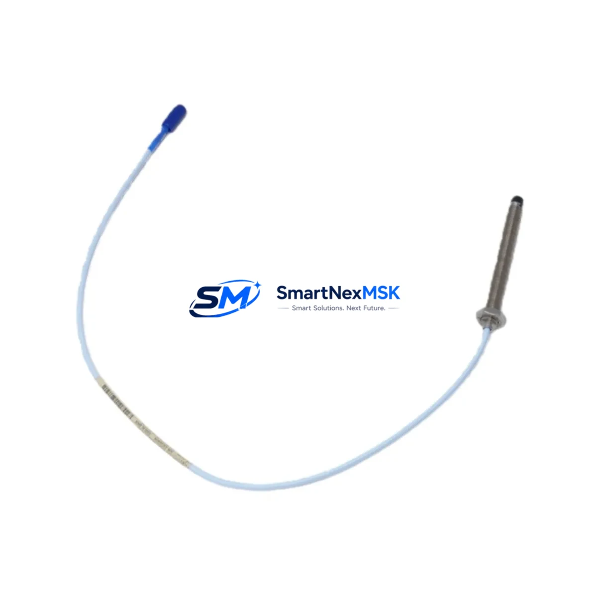
The Bently Nevada 330103-00-09-05-01-00 is an 8mm proximity probe engineered for the 3300 XL series continuous machinery monitoring platform. As legacy 3300 XL installations approach end-of-support cycles, this drop-in replacement probe enables seamless retrofit without requiring changes to existing field wiring, conduit routing, or monitor rack configurations. Whether you are upgrading a turbine protection panel, replacing a failed sensor on a compressor train, or modernizing a vibration monitoring loop on aging rotating equipment, this probe delivers the same signal characteristics and mechanical dimensions as the original factory part.
Before committing to a retrofit, engineers should verify several critical parameters. Power supply capacity at the rack level must accommodate the probe and its paired extension cable — typically the 330130-045-00-00 or 330130-080-00-00 extension cable — without exceeding the driver module’s output current budget. Terminal block wiring at the 3300/16 Monitor or 3300/20 Monitor should be inspected for correct polarity and shield grounding per Bently Nevada installation drawings. The probe tip gap must be set to the recommended 1.0 mm (approximately 7.87 Vdc output) using a calibrated gap tool before the system is returned to service.
For installations using the 3500/42M Proximitor/Seismic Monitor or migrating from older 3300 series racks to the 3500 platform, compatibility verification is essential. The 330103-00-09-05-01-00 operates within the standard Bently Nevada proximity system voltage range and is compatible with the 330180 Proximitor Sensor driver when used with the correct extension cable. If the existing rack uses a 3300/55 Dual Voting Monitor, confirm that the channel configuration and OK relay logic remain consistent after probe replacement.
Upgrade Compatibility Table
| Parameter | 330103-00-09-05-01-00 (This Unit) | Notes / Retrofit Guidance |
|---|---|---|
| Probe Diameter | 8 mm | Matches original 3300 XL field installation |
| Thread | M10 × 1.0 metric | No conduit or bracket modification required |
| Cable Length | 0.9 m (probe body) | Pair with 330130 series extension cable to reach driver |
| Compatible Monitor | 3300/16, 3300/20, 3500/42M | Verify channel slot assignment before installation |
| Compatible Driver | 330180 Proximitor Sensor | Check driver OK voltage range after gap setting |
| Signal Output | −200 mV/mil (−7.87 V/mm) | Confirm monitor input scaling matches |
| Communication Protocol | Analog (4–20 mA / voltage) | No protocol migration required for like-for-like swap |
| Installation Gap | 1.0 mm nominal | Set with calibrated gap tool; verify OK LED on driver |
| Warranty | 12 Months | Covers manufacturing defects; includes pre-shipment test report |
Retrofit Planning for Existing Automation Systems
A successful retrofit of the 330103-00-09-05-01-00 into an operating plant begins with a thorough audit of the existing monitoring loop. Start by documenting the current rack layout: identify the 3300 XL rack backplane slot assignments, confirm that the 3300/25 Power Supply or equivalent is delivering stable ±24 Vdc to the Proximitor driver, and photograph all terminal block connections before disconnecting any wiring.
If the plant is transitioning from a 3300 series rack to a 3500 Series Machinery Protection System, the probe itself is mechanically and electrically compatible, but the 3500/42M monitor card may require a different channel configuration file loaded via the Rack Configuration Software (RCS). Ensure that the 3500/01 Rack Interface Module firmware is current before importing the new configuration. For sites running System 1 Condition Monitoring Software, update the point configuration to reflect the new probe serial number and recalibrate the gap voltage reference in the historian.
In multi-probe installations — such as those monitoring X-Y vibration on a steam turbine bearing — both the radial probes and the 330103-00-09-05-01-00 axial or keyphasor probe should be replaced as a matched set where possible to maintain consistent sensitivity across the monitoring loop. The 330905-02-12-10-02-00 Keyphasor Probe is commonly replaced in the same outage window. Extension cables, particularly the 330130-045-00-00 (4.5 m) and 330130-080-00-00 (8.0 m) variants, should be inspected for jacket damage and connector corrosion; replace if continuity or insulation resistance is outside specification.
For control cabinets integrating both vibration monitoring and process control, verify that the 3300 XL rack shares a common instrument ground with the DCS or PLC chassis. Ground loops introduced during probe replacement are a frequent source of spurious OK relay trips. If the plant uses a Rockwell Automation ControlLogix or Siemens S7-300 PLC for interlock logic, confirm that the OK relay output from the Bently Nevada monitor is correctly mapped to the PLC input card before re-energizing the loop.
Downtime Control During System Migration
Minimizing unplanned downtime during a proximity probe replacement requires a structured pre-outage checklist. Before the maintenance window opens, pre-configure the replacement 330103-00-09-05-01-00 on a bench: set the gap voltage, verify the OK output, and document the as-found sensitivity. This allows the field team to complete the physical swap and gap setting within a single shift, reducing the risk of extended outage caused by troubleshooting at the rack.
To protect existing program logic, export a backup of the 3500 Rack Configuration or 3300 XL monitor settings before any hardware change. If the plant’s DCS — whether a Honeywell Experion PKS, Emerson DeltaV, or ABB 800xA — receives OK status from the Bently Nevada rack via Modbus or hardwired relay, place the affected interlock in bypass mode through the DCS safety override procedure before disconnecting the probe. This prevents a nuisance trip from interrupting production on adjacent equipment.
After installation, perform a live gap check with the shaft stationary, confirm the driver OK LED is illuminated, and verify that the vibration reading in the monitoring software is within the expected baseline range before releasing the bypass. Log the as-left gap voltage, probe serial number, and installation date in the plant maintenance management system (CMMS) to support future predictive maintenance scheduling.
Retrofit Support FAQ
Q1: Is the 330103-00-09-05-01-00 a direct drop-in replacement for the original Bently Nevada part?
Yes. This unit is manufactured to the same mechanical and electrical specifications as the original 330103-00-09-05-01-00. It uses the same M10 × 1.0 thread, 8 mm tip diameter, and −200 mV/mil sensitivity, making it a direct drop-in replacement without modification to existing conduit, brackets, or terminal wiring.
Q2: What wiring checks should be completed before installation?
Verify that the extension cable shield is grounded at one end only (typically at the driver/Proximitor end), confirm terminal polarity at the monitor card, and measure the driver supply voltage (should be within ±24 Vdc ±10%). Inspect the connector at the probe-to-extension cable junction for corrosion or mechanical damage before making up the connection.
Q3: How is compatibility with the 3500 Series platform confirmed?
The 330103-00-09-05-01-00 is electrically compatible with the 3500/42M Proximitor/Seismic Monitor when paired with a 330180 Proximitor driver. Confirm the monitor channel is configured for 8 mm probe sensitivity in the Rack Configuration Software, and perform a static gap calibration after installation to verify the OK output is within the monitor’s acceptance window.
Q4: What does the 12-month warranty cover, and is a test report included?
The 12-month warranty covers manufacturing defects in materials and workmanship from the date of shipment. Each unit ships with a pre-shipment functional test report confirming gap sensitivity, OK output voltage, and cable continuity. Warranty claims are processed via email with return authorization; replacement units are dispatched within 5 business days of confirmed fault diagnosis.
© 2026 SMARTNEXMSK. All rights reserved.
Original Source: https://smartnexmsk.com
Contact: sales@smartnexmsk.com | +86 18259474341


