Bently Nevada 330103-00-11-10-01-00 Spare 3300 XL Automation: Precision Spare Parts for Vibration Monitoring Downtime Control
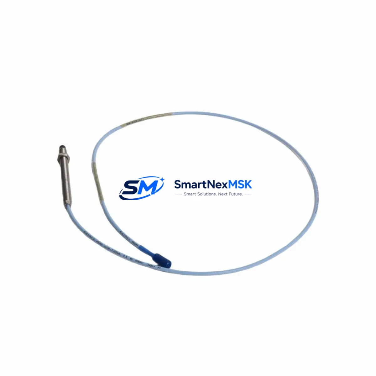
The Bently Nevada 330103-00-11-10-01-00 is an original 8mm proximity transducer engineered for the 3300 XL Series continuous vibration monitoring system. Designed for rotating machinery protection in turbines, compressors, pumps, and motors, this transducer delivers non-contact displacement measurement with the accuracy and reliability demanded by critical industrial assets. For maintenance engineers managing aging DCS or machinery protection systems, having a verified, tested spare of this transducer on the shelf is a fundamental risk-reduction strategy. Unplanned downtime caused by a failed proximity transducer can cascade into full-line shutdowns — sourcing a pre-tested replacement in advance is the most cost-effective insurance available.
This unit is supplied as an original spare, inspected and function-tested prior to shipment, and backed by a 12-month warranty. It is suitable for direct replacement in existing 3300 XL installations without system reconfiguration, provided the extension cable and proximitor are matched to the same series.
Spare Maintenance Table
| Parameter | Specification |
|---|---|
| Part Number | 330103-00-11-10-01-00 |
| Brand | Bently Nevada |
| Series | 3300 XL |
| Sensor Type | 8mm Proximity Transducer (Eddy Current) |
| Measurement | Radial Vibration / Axial Position / Speed |
| Output Signal | -18 VDC nominal (via proximitor) |
| Cable Length | 1.0m integral cable (extension cable required) |
| Thread Size | M10 x 1 |
| Temperature Range | -35°C to +177°C (probe tip) |
| Compatibility | 3300 XL Proximitor / Monitor System |
| Installation | Direct replacement; no recalibration required if gap is reset |
| Application | Turbines, Compressors, Pumps, Motors, Gearboxes |
| Origin | USA |
| Condition | Original Spare — Tested Before Shipment |
| Warranty | 12 Months |
Maintenance Planning for Continuous Operation
When a 330103-00-11-10-01-00 proximity transducer is flagged during routine vibration monitoring inspection or fails during a planned outage, the replacement scope should extend beyond the transducer itself. A complete maintenance review of the associated signal chain is strongly recommended to prevent repeat failures and ensure measurement integrity.
Start with the 3300 XL Extension Cable (typically 330130-series): inspect for jacket damage, connector corrosion, and continuity. A degraded cable is a common root cause of erratic vibration readings that are misattributed to the transducer. Next, verify the 3300 XL Proximitor / Seismic Monitor (such as the 3300/16 or 3300/20 monitor module) — check the proximitor output voltage and confirm it falls within the -18 VDC ±1 VDC operating window with the new transducer installed.
For installations in turbine control cabinets, simultaneously inspect the 3500 Series Rack Power Supply or equivalent DC power module supplying the monitoring loop. Voltage sag or ripple at the power supply level can introduce measurement noise that mimics transducer faults. Review the terminal blocks and field wiring in the junction box — loose terminations on the signal pair are a frequent source of intermittent alarms. If the system uses a signal isolator or barrier (common in hazardous area installations), verify the barrier’s input/output impedance is still within specification.
In DCS-integrated systems, confirm that the 4–20 mA output card or vibration I/O module receiving the proximitor signal is reading correctly after transducer swap. For older Bently Nevada 3300 racks, check the rack backplane connectors for oxidation. If the plant runs a System 1 Evolution or similar condition monitoring software, recalibrate the gap voltage reference in the software configuration after installation. Where keyphasor probes (such as the 330180-series) are co-located on the same shaft, inspect them during the same outage window — keyphasor signal quality directly affects phase-referenced vibration analysis.
Procurement engineers should consider stocking at least one spare transducer, one matched extension cable, and one proximitor module per critical machine train. This three-component spare kit approach eliminates the most common causes of extended downtime during emergency replacements.
Site Replacement Workflow
Step 1 — Isolation: Coordinate with operations to place the affected machine in a safe state. Isolate the monitoring loop at the junction box; do not disconnect at the monitor rack while the system is live unless the rack supports hot-swap.
Step 2 — Removal: Unthread the existing 330103-00-11-10-01-00 transducer using the correct spanner. Note the installed gap (typically 1.0–1.5mm for 8mm probes) using a feeler gauge or the proximitor output voltage reading before removal.
Step 3 — Installation: Thread the replacement transducer into the bracket. Set the gap to the original specification — typically targeting -10.0 VDC ±0.5 VDC at the proximitor output. Reconnect the extension cable and verify connector seating.
Step 4 — Verification: With the machine still isolated, power the monitoring loop and confirm the proximitor output voltage is within the linear range. Check for alarm or danger setpoint trips in the monitor. Clear any latched alarms.
Step 5 — Return to Service: Coordinate machine restart with operations. Monitor the first 30 minutes of operation for any vibration trend anomalies. Log the replacement in the CMMS with the new transducer serial number and gap setting.
This workflow is compatible with direct replacement of legacy 330103-series transducers and maintains full system compatibility with existing 3300 XL monitor configurations, eliminating the need for rack reconfiguration or software parameter changes.
Spare Parts Support FAQ
Q: Is the 330103-00-11-10-01-00 compatible with all 3300 XL monitor configurations?
A: Yes, provided the extension cable and proximitor are also 3300 XL series components. The transducer, extension cable, and proximitor must be ordered and used as a matched system. Mixing 3300 and 3300 XL components is not recommended and may affect calibration accuracy.
Q: How is the unit tested before shipment?
A: Each unit undergoes electrical continuity verification, coil resistance measurement, and output voltage confirmation using a calibrated proximitor driver. Units that do not meet OEM specification are rejected. A test report is available upon request.
Q: What is the recommended spare parts stocking strategy for this transducer?
A: For critical rotating machinery (turbines, compressors), maintain a minimum of one transducer per monitored bearing position as a cold spare. For non-critical assets, a shared pool of two to three units per site is typically sufficient. Shelf life in original packaging under controlled storage conditions exceeds five years.
Q: What does the 12-month warranty cover?
A: The warranty covers manufacturing defects and electrical failure under normal operating conditions for 12 months from the date of shipment. It does not cover damage resulting from incorrect installation, mechanical impact, or operation outside the specified temperature and voltage range. Warranty claims are processed with return of the defective unit for inspection.
© 2026 SMARTNEXMSK. All rights reserved.
Original Source: https://smartnexmsk.com
Contact: sales@smartnexmsk.com | +86 18259474341


