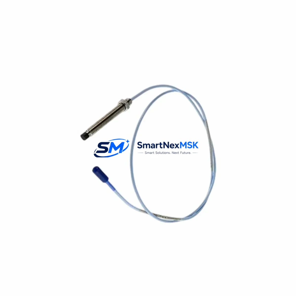
Bently Nevada 330103-00-11-10-02-00 Spare for 3300 XL Automation: Precision Replacement for Uninterrupted Vibration Monitoring
Unplanned downtime in rotating machinery environments is one of the most costly events in industrial operations. The Bently Nevada 330103-00-11-10-02-00 eddy current proximity probe is a critical sensing element within the 3300 XL Series continuous vibration monitoring system — a platform widely deployed across turbines, compressors, pumps, and generators in oil & gas, power generation, petrochemical, and heavy manufacturing facilities. When this probe degrades or fails, the entire vibration channel is compromised, leaving rotating assets unprotected and maintenance teams blind to developing faults.
This listing provides a maintenance-ready, original-specification spare for the 330103-00-11-10-02-00 proximity probe. Each unit is sourced, inspected, and dispatched with full traceability to support your planned maintenance intervals, emergency replacement events, and long-term spare parts inventory strategy.
Spare Maintenance Table
| Parameter | Specification |
|---|---|
| Part Number / SKU | 330103-00-11-10-02-00 |
| Brand | Bently Nevada |
| Series | 3300 XL Proximity Transducer System |
| Type | Eddy Current Proximity Probe |
| Probe Tip Diameter | 11 mm |
| Cable Length | 1.0 m (integral cable) |
| Extension Cable Compatibility | 3300 XL Extension Cable (e.g. 330130 series) |
| Driver / Proximitor Compatibility | 3300 XL 8mm Proximitor Sensor (330180 series) |
| Linear Range | 0.25 mm – 2.26 mm (10 – 89 mil) |
| Output Sensitivity | 7.87 V/mm (200 mV/mil) |
| Supply Voltage | -24 VDC (nominal) |
| Operating Temperature | -35°C to +177°C |
| Target Material | AISI 4140 steel or equivalent ferromagnetic alloy |
| Ingress Protection | IP67 (probe body) |
| Origin | USA |
| Application Environment | Turbines, compressors, pumps, gearboxes, generators |
| Mounting | Threaded bracket, radial or axial orientation |
| Compatibility Confirmation | Drop-in replacement for 330103-00-11-10-02-00; verify gap voltage and system calibration after installation |
| Pre-shipment Testing | Functional output and insulation resistance verified before dispatch |
| Warranty | 12 Months from date of shipment |
Maintenance Planning for Continuous Operation
For maintenance engineers managing 3300 XL-based vibration monitoring systems, replacing the 330103-00-11-10-02-00 probe is rarely an isolated task. A disciplined maintenance approach requires simultaneous inspection of the entire transducer chain and associated control cabinet components to prevent repeat failures and ensure channel integrity.
Begin with the 330130 series extension cable — the coaxial link between the probe and the Proximitor sensor. Extension cables are subject to mechanical fatigue, connector corrosion, and insulation breakdown, particularly in high-vibration or high-temperature zones. A degraded extension cable will produce erratic gap voltage readings even with a new probe installed. Inspect connector pins, cable jacket, and continuity before closing out the work order.
The 330180 series 3300 XL Proximitor Sensor (driver module) should be verified for correct bias voltage output (-10.0 VDC ± 0.5 VDC at the nominal gap). If the Proximitor is aged or has been exposed to voltage transients, it may require replacement alongside the probe to restore full channel accuracy. Keep at least one spare Proximitor per monitored machine train in your critical spares inventory.
Within the control cabinet, inspect the 3300 XL Rack power supply module supplying -24 VDC to the transducer system. Voltage ripple or supply sag will directly affect probe sensitivity and alarm thresholds. Use a calibrated multimeter to confirm supply rail stability before and after probe replacement. If the rack houses a 3300/16 or 3300/20 monitor card, verify that channel configuration, full-scale range, and alarm setpoints are correctly retained in non-volatile memory after any power interruption.
For facilities running integrated machinery protection, the 3500 series rack system may coexist with 3300 XL installations on the same machine train. During planned outages, cross-check that relay output modules, OK relay contacts, and system OK status signals are functioning correctly across both platforms. A failed OK relay in the 3300 XL rack can mask genuine vibration alarms at the DCS or PLC level.
Terminal blocks and field wiring within the junction box deserve attention during every probe replacement. Loose terminations on the signal pair or shield drain wire introduce noise that mimics real vibration signals. Inspect and re-torque all terminals, and verify that the cable shield is grounded at one end only, per Bently Nevada field wiring guidelines. Where signal runs exceed recommended lengths, a signal isolator or conditioner may be warranted to maintain signal integrity to the monitor rack.
Finally, if the machine is equipped with a Keyphasor transducer (typically a 330980 or 330905 series probe), verify its gap voltage and signal quality during the same maintenance window. The Keyphasor reference signal is essential for phase-referenced vibration analysis and balancing operations — a degraded Keyphasor will compromise the diagnostic value of all other vibration channels on the machine.
Site Replacement Workflow
Replacing the 330103-00-11-10-02-00 in the field follows a structured sequence designed to minimize downtime and eliminate re-work:
1. Pre-replacement verification: Confirm the replacement probe matches the original part number, cable length, and connector type. Cross-reference the system documentation or the existing probe label. Do not substitute with a different tip diameter or sensitivity variant without recalibrating the full channel.
2. Safe isolation: De-energize the Proximitor sensor supply at the rack before disconnecting the probe. This prevents electrostatic discharge damage to the Proximitor input circuitry. Tag out the channel at the monitor rack per your site LOTO procedure.
3. Mechanical removal and installation: Remove the probe from its mounting bracket, noting the original gap setting (typically recorded in the machine’s vibration baseline report). Install the replacement probe and set the gap to achieve the nominal bias voltage (-10.0 VDC ± 0.5 VDC). Use a non-conductive gap-setting tool to avoid scratching the probe tip or target surface.
4. System re-energization and channel verification: Re-energize the Proximitor supply and confirm bias voltage at the monitor rack input. Check that the channel OK status is active and that vibration readings are within expected baseline range. Compare against the machine’s historical vibration trend data before returning the channel to service.
5. Documentation: Record the replacement date, new probe serial number, gap voltage as-found and as-left, and any anomalies observed. Update the spare parts inventory to trigger replenishment of the consumed unit — maintaining a minimum of one probe per critical machine train is recommended practice for facilities operating under API 670 or equivalent machinery protection standards.
This workflow applies equally to scheduled turnaround replacements and emergency unplanned events, ensuring that system compatibility is maintained and that the machine returns to monitored operation with full channel confidence.
Spare Parts Support FAQ
Q1: Is this probe a direct drop-in replacement for the original 330103-00-11-10-02-00, or does it require recalibration?
This unit is supplied to original Bently Nevada specifications and is a direct mechanical and electrical replacement. However, as with any probe replacement, gap voltage must be verified and adjusted on-site after installation to account for minor dimensional tolerances in the mounting bracket and target surface. Full channel recalibration is recommended if the machine has been offline for an extended period or if the Proximitor sensor is also being replaced.
Q2: What is your recommended spare parts stocking strategy for 3300 XL proximity probes?
For critical rotating machinery (turbines, compressors, main pumps), we recommend holding a minimum of one probe per monitored channel as an on-site hot spare, with a secondary quantity held at the central warehouse. For non-critical or redundant machines, a pooled spare shared across similar machine types is acceptable. Given the lead times associated with specialty instrumentation, maintaining at least a 90-day forward stock is advisable for facilities with long procurement cycles.
Q3: How is each unit tested before shipment?
Every 330103-00-11-10-02-00 unit undergoes functional output verification (bias voltage and sensitivity check against a calibrated target) and insulation resistance testing of the cable and connector assembly prior to dispatch. Units that do not meet original specification are quarantined and not shipped. A test record is available upon request for quality-critical applications.
Q4: What does the 12-month warranty cover, and what is the claims process?
The 12-month warranty covers manufacturing defects, premature electrical failure under normal operating conditions, and out-of-specification output at the time of installation. It does not cover damage resulting from incorrect gap setting, mechanical impact, chemical exposure, or installation outside the specified operating parameters. To initiate a warranty claim, contact our technical support team with the order reference, installation date, and a description of the observed failure. Replacement units are dispatched upon claim approval, typically within 3–5 business days.
© 2026 SMARTNEXMSK. All rights reserved.
Original Source: https://smartnexmsk.com
Contact: sales@smartnexmsk.com | +86 18259474341


