Bently Nevada 330103-00-12-05-02-CN Maintenance-Ready Spare 3300 XL Automation
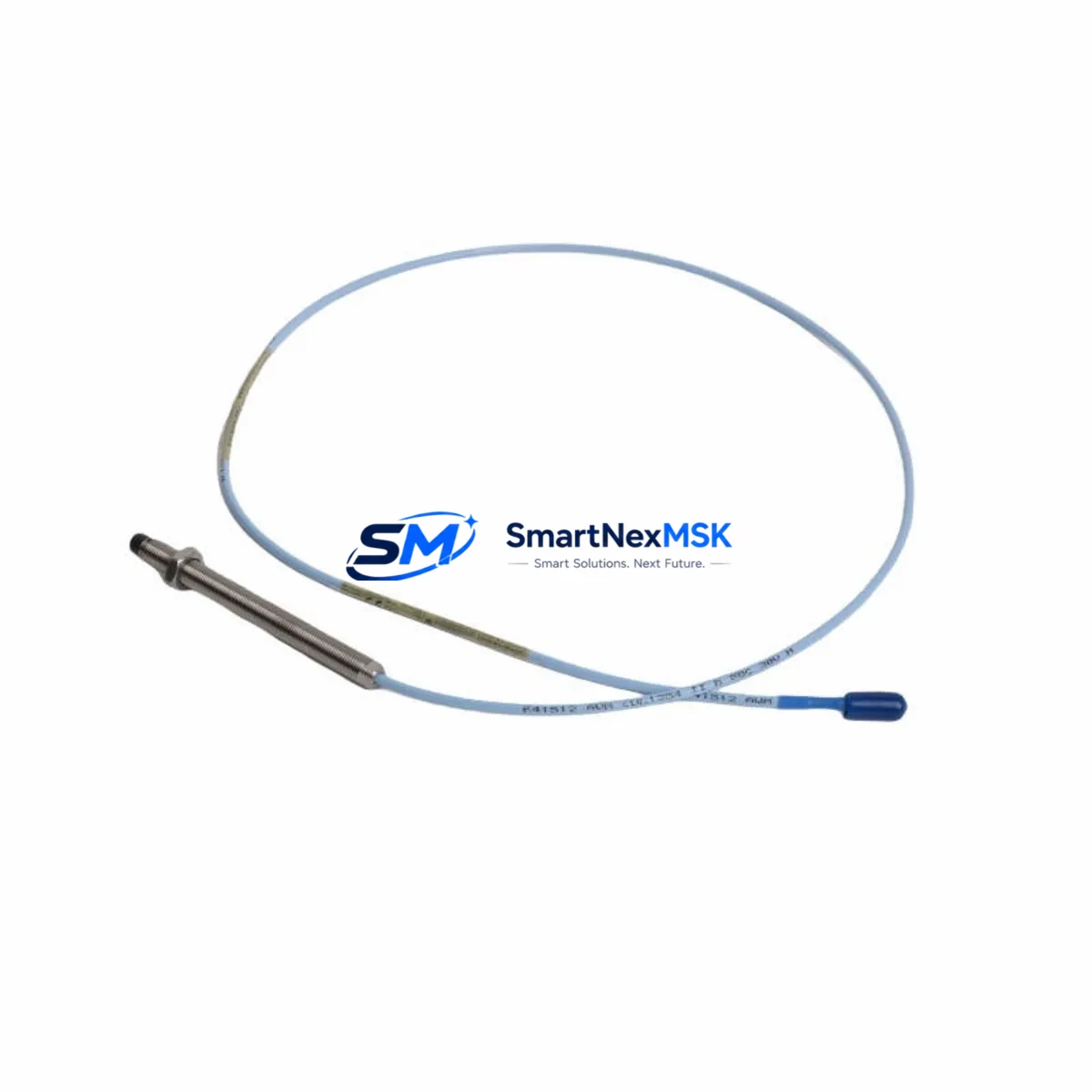
The Bently Nevada 330103-00-12-05-02-CN is an original 8mm proximity transducer engineered for the 3300 XL Series vibration monitoring system. In rotating machinery protection environments — turbines, compressors, pumps, and gearboxes — this probe is a critical front-line sensor responsible for continuous shaft displacement measurement. Unplanned failure of this component directly triggers machinery trip events, causing unscheduled downtime and production loss. Stocking a verified original spare is the most effective single action a maintenance team can take to reduce mean time to repair (MTTR) for vibration-related shutdowns.
This unit ships fully tested against Bently Nevada factory specifications, with dimensional, electrical, and signal output verification completed prior to dispatch. Each unit is backed by a 12-month warranty covering manufacturing defects and performance deviation from published specifications. Worldwide delivery is supported with export documentation available on request.
Spare Maintenance Table
| Parameter | Specification |
|---|---|
| Part Number | 330103-00-12-05-02-CN |
| Series | Bently Nevada 3300 XL |
| Probe Type | 8mm Eddy-Current Proximity Transducer |
| Sensitivity | 7.87 V/mm (200 mV/mil) |
| Linear Range | 0.25 mm – 2.54 mm (10–100 mil) |
| Operating Temperature | -35°C to +177°C |
| Cable Length | 0.5 m integral cable (extension cable required) |
| Connector | CN (Coaxial, metric) |
| Compatibility | 3300 XL 8mm System: Driver 330180, Extension Cable 330130 |
| Installation | M10 x 1 thread, jam-nut mounting |
| Application | Radial shaft vibration, axial position, differential expansion |
| Certification | CE, ATEX (zone-dependent — confirm with site classification) |
| Warranty | 12 Months from shipment date |
| Pre-shipment Test | Full electrical and signal output verification |
Maintenance Planning for Continuous Operation
When a 330103-00-12-05-02-CN probe is flagged for replacement during a planned outage or emergency shutdown, experienced maintenance engineers treat the event as a trigger for a broader loop inspection. The 3300 XL proximity measurement chain is a system — probe, extension cable, and driver — and degradation rarely occurs in isolation.
Begin by inspecting the 330130 extension cable for jacket abrasion, connector corrosion, or crush damage from cable trays. A compromised extension cable introduces gap voltage drift that mimics probe failure and is a common misdiagnosis. Next, verify the 330180 proximitor/driver module seated in the monitor rack: check the output voltage at the OK relay terminal and confirm the gap voltage sits within the 3300 XL linear range before declaring the probe as the root cause.
At the monitor rack level, inspect the 3300/16 or 3500/42 vibration monitor card for alarm setpoint integrity and relay output continuity. If the site runs a 3500 Series rack, confirm the 3500/20 rack interface module communication status and verify that the 3500/92 communication gateway is correctly forwarding trip data to the DCS or SCADA historian. Corrupted trip logs during a probe swap can mask recurring faults.
For sites with older installations, check the 330100 series standard probe inventory alongside the 330103 XL variant — mixed probe generations on the same shaft are a known source of sensitivity mismatch alarms. Confirm that all probes on a given machine train share the same series and sensitivity specification.
Power supply integrity is equally important: the -24 VDC proximitor supply rail should be measured under load. A sagging supply rail causes false OK-relay dropout and can be misread as probe failure. If the site uses a dedicated Bently Nevada 3300/05 power supply module, inspect the output terminals and fuse condition. Terminal blocks and DIN-rail mounted fuse holders in the junction box should be torqued to specification and inspected for oxidation, particularly in humid or coastal environments.
For machinery with both radial and axial measurement requirements, the axial 330103 thrust probe and its paired 330130 extension cable should be replaced as a matched set whenever one component is renewed, to maintain calibrated gap voltage consistency across the measurement plane. Document the as-found and as-left gap voltages in the maintenance management system to establish a baseline for the next inspection interval.
Site Replacement Workflow
Step 1 — Isolation and permit: Obtain a lock-out/tag-out permit for the machinery train. Confirm the 3300 XL monitor is in bypass mode to prevent spurious trips during probe removal.
Step 2 — As-found documentation: Record the existing gap voltage (target: -10.0 VDC ±0.5 V for standard 8mm gap), probe serial number, and cable routing before disassembly. Photograph the probe tip condition and any observable shaft surface wear at the measurement zone.
Step 3 — Removal: Back off the jam nut (M10 x 1) and unthread the probe body. Inspect the probe tip for impact damage or contamination. Inspect the shaft surface for scoring — a damaged observation area will corrupt readings from the replacement probe regardless of its condition.
Step 4 — Installation of 330103-00-12-05-02-CN: Thread the new probe to the manufacturer-specified gap (typically 1.0–1.5 mm from shaft surface for initial setup). Connect the CN-type coaxial connector to the 330130 extension cable. Verify connector seating and apply thread-locking compound to the jam nut per site procedure.
Step 5 — Commissioning verification: With the machine stationary, measure the gap voltage at the driver output. Adjust probe gap until the output reads within the linear range center. Record the as-left gap voltage. Remove bypass, confirm OK relay energizes, and verify the monitor displays a valid vibration reading before releasing the machine to operations.
Step 6 — Documentation and spare replenishment: Update the CMMS with the replacement record and immediately initiate a purchase order to replenish the consumed spare. A single-unit spare inventory for a critical probe is insufficient for sites with multiple measurement points — a minimum of two units per machine train is the recommended stocking level.
Spare Parts Support FAQ
Q: Is the 330103-00-12-05-02-CN a direct drop-in replacement for the 330103-00-12-05-02?
A: The CN suffix designates the coaxial connector variant. Confirm your existing extension cable (330130) uses the matching CN-type connector before ordering. If your installation uses a different connector suffix, contact us to confirm compatibility or source the correct variant.
Q: What is the recommended spare stocking strategy for 3300 XL proximity probes?
A: For critical rotating machinery (turbines, compressors), maintain a minimum of two probes per machine train plus one driver module (330180) as a cold spare. For non-critical applications, one probe per measurement point is acceptable. Probes stored in original packaging in a climate-controlled environment maintain specification for a minimum of five years.
Q: How is each unit tested before shipment?
A: Every 330103-00-12-05-02-CN unit undergoes bench testing including coil resistance measurement, insulation resistance check, and functional gap voltage verification using a calibrated 3300 XL driver. A test report is available on request. Units that do not meet Bently Nevada published specifications are not shipped.
Q: What does the 12-month warranty cover?
A: The warranty covers manufacturing defects and performance deviation from published Bently Nevada specifications under normal operating conditions. It does not cover damage resulting from incorrect installation gap, shaft surface contact, connector over-torque, or exposure to conditions outside the rated temperature and chemical resistance envelope. Warranty claims are processed with return of the defective unit and a completed failure description form.
© 2026 SMARTNEXMSK. All rights reserved.
Original Source: https://smartnexmsk.com
Contact: sales@smartnexmsk.com | +86 18259474341


