Bently Nevada 330103-00-12-10-12-00 Maintenance-Ready Spare 3300 XL Automation
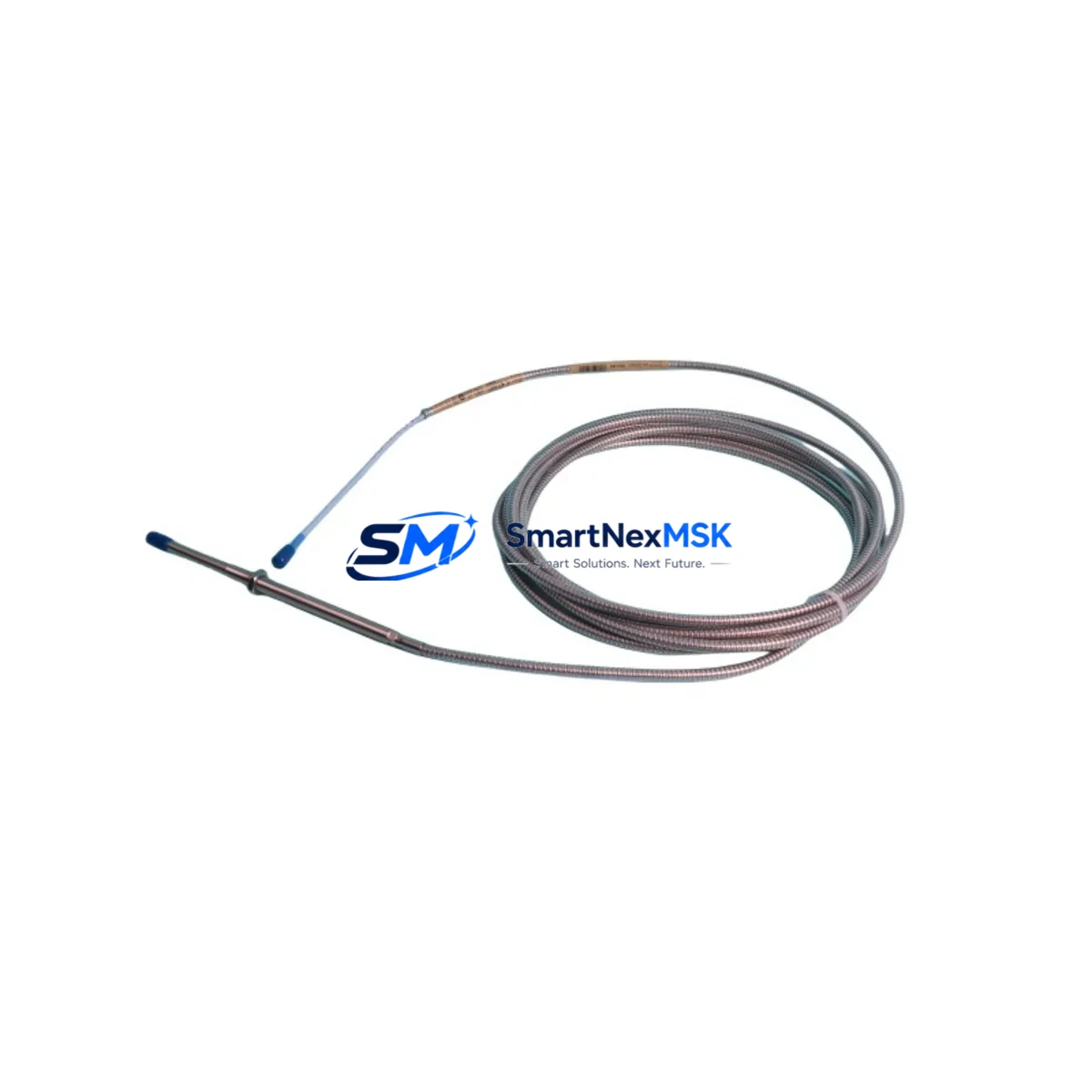
The Bently Nevada 330103-00-12-10-12-00 is an original eddy-current proximity transducer engineered for the 3300 XL continuous machinery monitoring system. Designed for radial vibration, axial position, and differential expansion measurement on rotating machinery, this transducer is a critical spare for turbines, compressors, pumps, and other high-value rotating assets in oil & gas, power generation, petrochemical, and heavy industrial facilities.
For maintenance engineers managing planned outages or responding to unplanned shutdowns, having a verified, tested replacement of the 330103-00-12-10-12-00 on the shelf is the single most effective way to minimize mean time to repair (MTTR). This unit ships fully tested, with a 12-month warranty, and is compatible with the Bently Nevada 3300 XL monitoring rack architecture.
Procurement engineers sourcing this part for critical asset protection programs can rely on our long-term supply capability, documented traceability, and pre-shipment functional verification. We maintain stock to support both emergency breakdown orders and scheduled maintenance intervals.
Spare Maintenance Table
| Part Number | 330103-00-12-10-12-00 |
| Brand | Bently Nevada |
| Series | 3300 XL |
| Product Type | Eddy-Current Proximity Transducer |
| Measurement Function | Radial vibration, axial position, differential expansion |
| Cable Length | 12 inches (extension cable compatible) |
| Thread Size | 10-32 UNF |
| Gap Range | 0–90 mil (0–2.29 mm) |
| Output Sensitivity | 200 mV/mil (7.87 V/mm) |
| Operating Temperature | -35°C to +177°C (sensor tip) |
| Compatible Monitor | Bently Nevada 3300 XL Series Rack |
| Compatible Extension Cable | 330130 Series |
| Compatible Proximitor | 330180 / 330185 Series |
| Origin | USA |
| Installation Environment | Hazardous area rated; suitable for turbine bearing housings, compressor pedestals |
| Warranty | 12 Months |
| Pre-Shipment Test | Yes — functional and dimensional verification |
| Availability | In stock; emergency orders supported |
Maintenance Planning for Continuous Operation
When replacing the 330103-00-12-10-12-00 proximity transducer during a planned outage or emergency shutdown, a thorough inspection of the surrounding measurement chain and control cabinet components is essential to prevent repeat failures and ensure system integrity.
Begin with the 330130 Series extension cable — the coaxial cable connecting the transducer to the proximitor. Cable insulation degradation, connector corrosion, or mechanical damage from vibration fatigue are common failure modes that can mimic transducer faults. Replace the extension cable as a matched set whenever the transducer is changed.
Next, verify the condition of the 330180 or 330185 Proximitor sensor. The proximitor provides the oscillator/demodulator function and is calibrated as a system with the transducer and cable. A mismatched or aging proximitor will produce inaccurate gap voltage readings even with a new transducer installed. Confirm the system sensitivity and bias voltage at the monitor input after installation.
At the 3300 XL monitor rack level, inspect the relevant I/O module and signal conditioning cards. Check the 3300/16 or 3300/20 series monitor modules for alarm setpoint integrity, OK relay status, and buffered output signal quality. A failing monitor card can mask a healthy transducer or generate spurious trips.
For the power supply feeding the 3300 XL rack, inspect the 3300/05 power supply module for output voltage stability. Voltage ripple or dropout events can corrupt proximity measurements and trigger nuisance alarms. If the rack has been in service for more than five years, consider proactive replacement of the power supply module during the same outage window.
In the control cabinet, inspect terminal blocks and field wiring for oxidation, loose terminations, and moisture ingress — particularly in high-vibration or high-humidity environments. Verify that cable shielding is properly grounded at a single point to prevent ground loops that introduce noise into the proximity signal.
If the machine is also equipped with a Keyphasor transducer (typically a 330980 or 330900 series), verify its gap and signal output during the same maintenance window. The Keyphasor reference signal is used by the 3300 XL system for phase and speed measurements, and a degraded Keyphasor will affect the accuracy of all vibration vectors.
For facilities running System 1 or System 1 Evolution condition monitoring software, confirm that the new transducer’s calibration data is correctly entered and that the software is receiving valid dynamic data after installation. Update the asset configuration record to reflect the replacement date and new serial number.
Finally, review the spare parts inventory for 3300 XL rack communication modules and any relay output modules used for machinery protection trip logic. These components are often overlooked in spare parts planning but are equally critical to system availability.
Site Replacement Workflow
Step 1 — Isolation and Lockout: Follow site LOTO procedures. De-energize the 3300 XL rack channel associated with the transducer being replaced. Note the existing gap voltage (bias voltage) reading from the monitor before disconnection — this is your baseline for reinstallation verification.
Step 2 — Transducer Removal: Disconnect the extension cable at the proximitor end. Unthread the 330103-00-12-10-12-00 from the bearing housing bracket. Inspect the mounting threads and bracket for wear or damage. Clean the target area and measure the target surface runout if accessible.
Step 3 — New Transducer Installation: Install the replacement 330103-00-12-10-12-00 and set the initial gap to the manufacturer-specified nominal value (typically 50 mil / 1.27 mm for standard steel targets). Use a calibrated gap-setting tool or feeler gauge. Reconnect the matched 330130 extension cable and verify connector seating.
Step 4 — System Verification: Re-energize the channel and measure the bias voltage at the monitor input. Confirm the reading falls within the OK window (typically -10 VDC ±1 VDC for standard gap). Check the monitor OK LED status and verify that no alarms are active at the normal operating gap.
Step 5 — Dynamic Verification: During machine restart, observe the vibration trend and compare with historical baseline data. Confirm that the new transducer is tracking correctly and that no spurious spikes or dropouts are present in the buffered output signal.
This workflow is compatible with both direct replacement of legacy 330103 series transducers and upgrade scenarios where older non-XL transducers are being replaced with 3300 XL-compatible units. The 330103-00-12-10-12-00 is a direct functional replacement for earlier Bently Nevada 7200 series transducers of equivalent cable length and thread specification, subject to system calibration verification.
Spare Parts Support FAQ
Q: Is the 330103-00-12-10-12-00 compatible with older Bently Nevada 3300 series racks (non-XL)?
A: The 330103-00-12-10-12-00 is designed and calibrated for the 3300 XL system. While the physical connector and thread specification may be compatible with earlier 3300 series hardware, system sensitivity and OK voltage windows differ between XL and non-XL generations. Always verify bias voltage and sensitivity with the specific monitor module in use before returning the machine to service.
Q: How do you verify the transducer before shipment?
A: Each unit undergoes functional verification including bias voltage output check, sensitivity confirmation, and physical inspection of the tip, body, and connector. Units that do not meet Bently Nevada specification are not shipped. A 12-month warranty covers defects in materials and workmanship from the date of shipment.
Q: Can you supply the complete measurement chain — transducer, extension cable, and proximitor — as a matched set?
A: Yes. We recommend ordering the 330103-00-12-10-12-00 transducer together with the appropriate 330130 series extension cable and 330180/330185 proximitor as a calibrated system set. This eliminates sensitivity mismatch risk and simplifies site installation and verification.
Q: What is your lead time for emergency orders?
A: In-stock units are available for same-day or next-business-day dispatch. For emergency breakdown situations, contact our sales team directly to confirm availability and arrange priority shipment. We support both domestic and international emergency supply requirements.
© 2026 SMARTNEXMSK. All rights reserved.
Original Source: https://smartnexmsk.com
Contact: sales@smartnexmsk.com | +86 18259474341


