Bently Nevada 330103-00-13-10-01-00 Retrofit-Ready Proximity Transducer for 3300 XL Control Systems
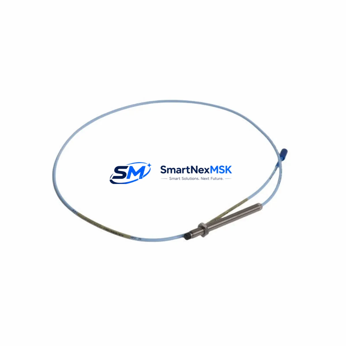
The Bently Nevada 330103-00-13-10-01-00 is an 8 mm proximity transducer engineered for seamless integration into existing 3300 XL Series vibration monitoring systems. As legacy Bently Nevada 3300 Series components approach end-of-life or become increasingly difficult to source, this retrofit-ready transducer provides a verified drop-in replacement path that preserves your existing wiring infrastructure, conditioner compatibility, and monitoring logic — minimizing engineering rework and unplanned downtime during system modernization.
Designed for continuous shaft vibration, radial position, and axial thrust measurement in rotating machinery, the 330103-00-13-10-01-00 operates within the standard Bently Nevada TK-3 extension cable and 3300 XL proximitor/sensor system architecture. Engineers migrating from earlier 3300 Series transducers or decommissioned 7200 Series probes will find this unit fully compatible with the 3300 XL 8 mm Proximitor Sensor (330180 series), eliminating the need for signal recalibration in most standard gap voltage configurations.
Upgrade Compatibility Table
| Parameter | Details |
|---|---|
| SKU / Part Number | 330103-00-13-10-01-00 |
| Series Compatibility | Bently Nevada 3300 XL Series |
| Replaces / Supersedes | 3300 Series 8 mm probes; 7200 Series legacy transducers |
| Probe Diameter | 8 mm |
| Cable Length | 1.0 m integral cable (TK-3 compatible) |
| Thread | M10 x 1.0 |
| Connector Type | 3-pin MIL-C-5015 compatible |
| Proximitor Compatibility | 330180 Series 3300 XL 8 mm Proximitor Sensor |
| Communication / Signal | Analog DC voltage (gap voltage output, -18 VDC nominal) |
| Installation Requirement | Standard 3300 XL bracket; no new mounting hardware required |
| Calibration | Factory-calibrated; field gap setting required (1.0 mm nominal) |
| Retrofit Recommendation | Direct replacement; verify extension cable length and proximitor model |
| Commissioning Note | Confirm gap voltage at -10.0 VDC ±0.5 V before returning to service |
| Warranty | 12-Month Warranty included |
Retrofit Planning for Existing Automation Systems
When planning a retrofit involving the 330103-00-13-10-01-00, a structured approach to component verification is essential. Begin by auditing the existing proximitor — typically a 330180-51-00 or 330180-91-00 — to confirm it remains within calibration tolerance and that its power supply rail (typically -24 VDC from a dedicated proximitor power supply module) is stable. If the proximitor itself is flagged for replacement, the 330180 Series 3300 XL 8 mm Proximitor Sensor is the recommended companion unit and can be swapped without rewiring the junction box terminal strip.
Extension cable integrity is a frequent failure point in aging systems. The TK-3 Series extension cables — available in standard lengths from 1 m to 9 m — should be inspected for jacket cracking, connector corrosion, and continuity before reuse. In many retrofit scenarios, replacing the extension cable alongside the transducer eliminates intermittent signal faults that would otherwise require repeated field visits.
For systems integrated with a Bently Nevada 3500 Series rack — including the 3500/42M Proximitor/Seismic Monitor or the 3500/40M Proximitor/Seismic Monitor — the transducer output feeds directly into the monitor card’s channel input. Verify that the channel configuration in the 3500 rack software (Rack Configuration Utility) reflects the correct transducer scale factor (200 mV/mil or 7.87 V/mm) before re-enabling the channel. Mismatched scale factors are a common source of false alerts during commissioning.
In plants running a hybrid architecture — where legacy 3300 Series monitors coexist with newer 3500 Series racks or a System 1 condition monitoring platform — the 330103-00-13-10-01-00 supports both environments without signal conditioning adapters. This makes it particularly valuable in phased upgrade programs where full rack replacement is deferred to a future outage window.
For control cabinets that also house a Bently Nevada 3500/20 Power Supply Module or a 3500/15 Power Supply, confirm that the total transducer load does not exceed the supply’s rated output current. In dense I/O configurations with multiple proximity channels, adding a supplemental 3500/20 module may be necessary before expanding the transducer count. Similarly, if the cabinet includes a 3500/92 Communication Gateway Module for Modbus or Ethernet/IP integration, verify that the new channel mapping is reflected in the gateway’s register table to avoid data gaps in the DCS historian.
Plants using a GE/Emerson Ovation DCS or a Honeywell Experion PKS as the supervisory layer should confirm that the analog input card receiving the proximitor output — often a legacy 4–20 mA converted signal via a signal conditioner — is correctly scaled in the DCS engineering unit configuration. Updating the HMI faceplate tag descriptor and alarm setpoints in the DCS graphics is a mandatory step before returning the machine train to service.
Downtime Control During System Migration
Minimizing production impact during a proximity transducer retrofit requires pre-staging all replacement components — including the 330103-00-13-10-01-00 transducer, TK-3 extension cable, and any required proximitor — at the work site before the maintenance window opens. A pre-verified spare, bench-tested against a known-good proximitor with gap voltage confirmed at -10.0 VDC ±0.5 V, eliminates the risk of discovering a defective unit after the machine is already offline.
Where possible, use the 3500 rack’s channel bypass or inhibit function to suppress alarms on the affected channel during the swap, preventing nuisance trips to the safety system or DCS. Document the original gap measurement, cable routing, and terminal identification before disconnecting any wiring. Photograph the junction box terminal strip and the proximitor mounting bracket orientation to support rapid reassembly.
After installation, perform a static gap check with the shaft stationary, then a dynamic check at operating speed to confirm that the vibration reading is within the expected baseline range. Compare the live channel reading in System 1 or the 3500 rack display against the pre-outage trend data to validate that the replacement transducer is performing within specification. Only after this verification should the channel inhibit be removed and the machine returned to normal monitored operation.
For sites with strict change management requirements, prepare a pre-approved Method of Procedure (MOP) that references the 330103-00-13-10-01-00 part number, the associated proximitor model, and the expected gap voltage range. This documentation supports rapid approval cycles and provides a clear audit trail for reliability engineers and plant safety reviews.
Retrofit Support FAQ
Q: Is the 330103-00-13-10-01-00 a direct drop-in replacement for earlier 3300 Series 8 mm probes?
A: Yes. The 330103-00-13-10-01-00 is dimensionally and electrically compatible with standard 3300 Series 8 mm proximity probes. Verify thread engagement depth and extension cable connector type before installation. No signal recalibration is required if the proximitor model and gap setting remain unchanged.
Q: What commissioning steps are required after replacing the transducer?
A: After mechanical installation, set the probe gap to the nominal 1.0 mm (approximately -10.0 VDC output). Confirm the gap voltage at the proximitor output terminals using a calibrated multimeter. Re-enable the monitor channel in the 3500 rack or legacy 3300 monitor, verify the vibration reading against baseline, and remove any channel inhibits before returning the machine to service.
Q: Can this transducer be used with a 3500 Series rack as well as legacy 3300 monitors?
A: Yes. The 330103-00-13-10-01-00 is compatible with both the legacy 3300 Series monitoring system and the current 3500 Series rack platform, including the 3500/42M and 3500/40M monitor cards. Confirm the channel scale factor setting in the rack configuration software matches the transducer’s output sensitivity.
Q: What warranty and pre-shipment testing does SMARTNEXMSK provide?
A: Every 330103-00-13-10-01-00 unit ships with a 12-month warranty covering manufacturing defects and functional performance. Pre-shipment testing includes gap voltage output verification, insulation resistance check, and connector integrity inspection. A test report is available upon request. Contact sales@smartnexmsk.com for expedited orders or technical pre-sales support.
© 2026 SMARTNEXMSK. All rights reserved.
Original Source: https://smartnexmsk.com
Contact: sales@smartnexmsk.com | +86 18259474341


