Bently Nevada 330103-00-14-50-02-00 Spare 3300 XL Automation: Spare Replacement & Industrial Downtime Risk Control
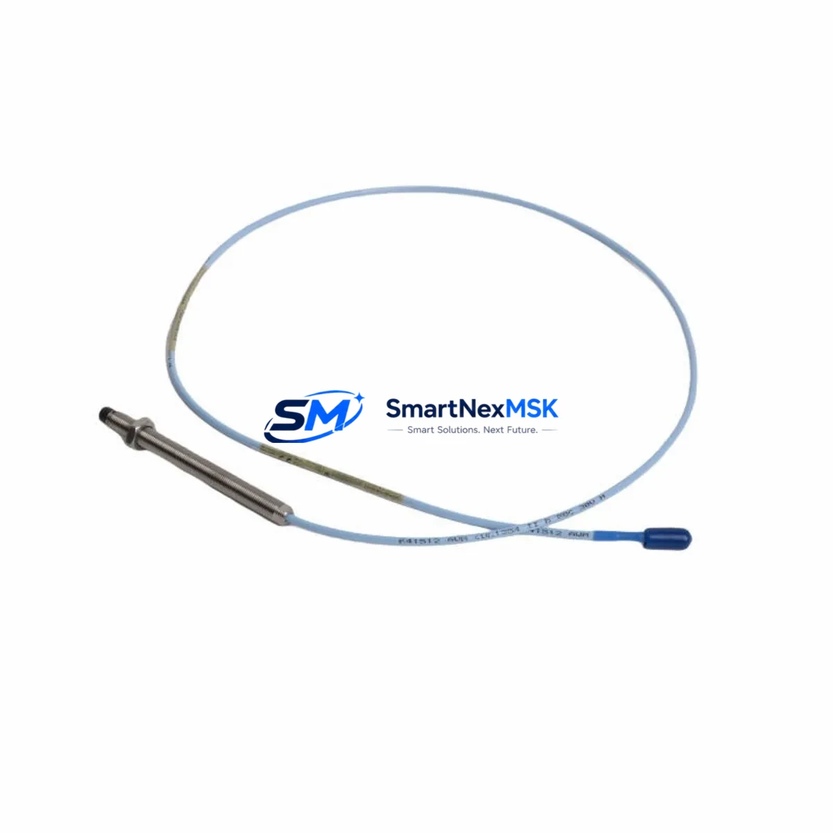
The Bently Nevada 330103-00-14-50-02-00 is a 5mm proximity transducer engineered for the 3300 XL Series continuous machinery monitoring system. As a maintenance-ready original spare, this transducer is a critical component in vibration measurement loops used across rotating machinery — including steam turbines, compressors, pumps, and gearboxes — in oil & gas, power generation, petrochemical, and heavy industrial facilities.
When a proximity transducer fails or drifts out of calibration, the entire vibration monitoring channel becomes unreliable, exposing the machine to undetected bearing wear, shaft misalignment, or rotor instability. Unplanned downtime in these environments can cost tens of thousands of dollars per hour. Stocking the 330103-00-14-50-02-00 as a certified spare eliminates lead-time risk and enables same-shift replacement during fault isolation or planned outage windows.
This unit is supplied as an original Bently Nevada component, fully tested prior to shipment, and backed by a 12-month warranty. It is compatible with the 3300 XL 5mm Proximity Transducer System and integrates directly with the standard 3300 XL extension cable and proximitor/oscillator driver assemblies without requiring system reconfiguration.
Spare Maintenance Table
| Parameter | Specification |
|---|---|
| Part Number / SKU | 330103-00-14-50-02-00 |
| Brand | Bently Nevada |
| Series | 3300 XL 5mm Proximity Transducer System |
| Transducer Type | Eddy-Current Proximity Transducer |
| Tip Diameter | 5mm |
| Cable Length | 1.4m (integral cable) |
| Thread Size | M10 x 1 |
| Sensitivity | 7.87 V/mm (200 mV/mil) |
| Linear Range | 0.25 – 2.25 mm (10 – 90 mil) |
| Supply Voltage | -24 VDC (via proximitor) |
| Operating Temperature | -35°C to +177°C |
| Connector Type | Integral coaxial cable with TNC connector |
| Compatible Proximitor | 3300 XL 8mm / 5mm Proximitor/Oscillator |
| Compatible Extension Cable | 330130 Series (5mm system) |
| Application Environment | Rotating machinery, turbines, compressors, pumps |
| Maintenance Recommendation | Replace at first sign of output drift, gap voltage anomaly, or physical cable damage |
| Origin | USA |
| Warranty | 12 Months |
| Pre-shipment Testing | Yes — functional and output verification |
Maintenance Planning for Continuous Operation
Effective maintenance of a 3300 XL vibration monitoring loop requires more than replacing the transducer in isolation. When a 330103-00-14-50-02-00 is flagged for replacement — whether during a scheduled outage, a routine control cabinet inspection, or an emergency fault response — maintenance engineers should simultaneously verify the condition of all interdependent components in the measurement chain.
The 330130-080-00-00 extension cable (5mm system, 8m) is the most common wear point after the transducer itself. Inspect for jacket cracking, connector corrosion, and continuity. A degraded cable will introduce noise into the gap voltage signal even with a new transducer installed. Similarly, the 3300 XL Proximitor/Oscillator (typically the 330180 or 330185 series) should be bench-tested for output linearity and supply current draw — a failing proximitor will cause the replacement transducer to read incorrectly from day one.
At the rack level, confirm that the 3500/42M Proximitor I/O Module or equivalent 3300 series I/O card is seated correctly and that its channel configuration matches the new transducer’s sensitivity constant. If the facility uses a 3500/20 Rack Interface Module for Modbus or Ethernet communication, verify that the rack communication link is active and that alarm setpoints have not been inadvertently reset during the maintenance window.
Power supply integrity is equally critical. The 3500/15 Power Supply Module should be checked for output voltage stability under load — a sagging -24 VDC rail will cause proximity system errors that mimic transducer failure. If dual redundant power supplies are installed, test the automatic switchover function. Fuse holders and terminal blocks on the field wiring side should be inspected for oxidation, especially in humid or coastal environments.
For facilities running legacy 3300 Series (non-XL) racks alongside newer 3500 infrastructure, confirm that the replacement transducer’s sensitivity and gap range are compatible with the older rack’s channel cards before installation. Cross-series substitution without verification is a common source of post-maintenance alarm nuisance trips. Where HMI integration is in use — such as a System 1 Evolution condition monitoring workstation — confirm that the channel tag mapping and engineering unit scaling are updated to reflect any transducer substitution.
Finally, document the as-found gap voltage and the as-left gap voltage in the maintenance record. This baseline data is essential for trend analysis and for validating that the replacement transducer is correctly positioned within its linear range before the machine is returned to service.
Site Replacement Workflow
Step 1 — Isolation & Lockout: De-energize the proximitor supply to the affected channel. Confirm zero voltage at the transducer connector before disconnecting. Do not rely on rack-level inhibit alone for physical cable work.
Step 2 — As-Found Documentation: Record the existing gap voltage (typically displayed on the 3500 rack front panel or System 1 HMI), the physical gap measurement, and any visible damage to the transducer tip or cable jacket. Photograph the installation before removal.
Step 3 — Transducer Removal: Loosen the locknut and unthread the transducer from the bracket. Note the number of turns required to reach the as-found gap — this provides a starting reference for the replacement installation. Disconnect the extension cable at the TNC connector.
Step 4 — Replacement Installation: Thread the 330103-00-14-50-02-00 into the bracket to the approximate as-found depth. Reconnect the extension cable. Re-energize the proximitor and measure the output voltage. Adjust the transducer gap until the output falls within the linear range midpoint (typically -10 to -11 VDC for a 1.0mm gap on a 5mm system). Tighten the locknut to the specified torque.
Step 5 — System Verification: Clear any latched alarms at the rack. Confirm that the channel reads correctly on the System 1 or DCS display. Perform a slow-roll check if the machine can be rotated before full restart. Log the as-left gap voltage and return the channel to normal monitoring mode.
This workflow minimizes downtime, preserves system compatibility, and ensures the replacement transducer is operating within its specified performance envelope before the machine returns to full load.
Spare Parts Support FAQ
Q1: Is the 330103-00-14-50-02-00 a direct drop-in replacement for older 330103 variants?
A: The 330103-00-14-50-02-00 is part of the 3300 XL 5mm transducer family. It is dimensionally and electrically compatible with other 330103 suffix variants in the same cable-length and connector configuration. However, always verify the extension cable length and proximitor model before substitution, as sensitivity constants and gap ranges must match the installed system configuration.
Q2: How should this spare be stored to maintain its service life?
A: Store in the original packaging or an anti-static, moisture-resistant bag at temperatures between -20°C and +70°C. Avoid coiling the integral cable tightly, as this can stress the coaxial core. Inspect the TNC connector for contamination before installation. Shelf life under proper storage conditions exceeds five years.
Q3: What pre-shipment testing is performed on this unit?
A: Each 330103-00-14-50-02-00 unit is functionally tested for output voltage linearity, gap sensitivity, and connector integrity before shipment. A test report is available upon request. The 12-month warranty covers manufacturing defects and performance deviations from the published specification under normal operating conditions.
Q4: Can this transducer be used in a 3500 Series rack system?
A: Yes. The 3300 XL 5mm proximity transducer system is compatible with 3500 Series rack I/O modules configured for 5mm transducer input. Confirm the channel configuration in the 3500 Rack Configuration Software (RCS) matches the 330103 sensitivity constant (7.87 V/mm) before commissioning the replacement channel.
© 2026 SMARTNEXMSK. All rights reserved.
Original Source: https://smartnexmsk.com
Contact: sales@smartnexmsk.com | +86 18259474341


