Bently Nevada 330103-00-19-10-01-00 Retrofit-Ready Proximity Transducer for 3300 XL Control Systems
The Bently Nevada 330103-00-19-10-01-00 is a high-precision eddy-current proximity transducer engineered for the 3300 XL Series continuous machinery monitoring platform. As aging 3300 Series installations approach end-of-service life and OEM support windows close, this module provides a verified, drop-in retrofit path that preserves existing wiring infrastructure, rack architecture, and monitor calibration — minimising both capital expenditure and planned downtime during system modernisation.
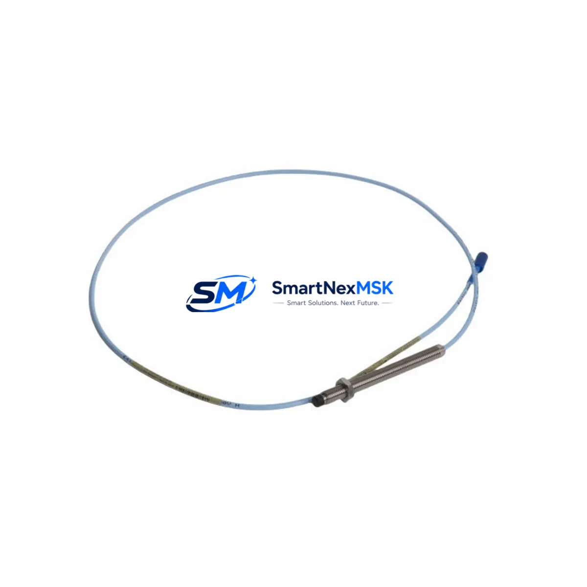
Designed for radial vibration, axial position, and eccentricity measurement on rotating machinery, the 330103-00-19-10-01-00 operates within the standard Bently Nevada signal chain: transducer → extension cable → Proximitor® sensor → 3300 XL monitor card. When replacing a failed or obsolete transducer in an operating train, engineers must verify tip diameter, probe body length (19 mm in this configuration), cable length (10 ft), and connector type before installation to ensure the replacement integrates without recalibration of the associated 3300 XL/16 or 3300 XL/01 monitor modules.
Procurement teams sourcing this part as a critical spare should confirm that the Proximitor® sensor paired in the field — typically a 330180 or 330130 series — is matched to the same gap voltage range. Mismatched Proximitor® sensors are the most common cause of post-replacement alarm drift and must be addressed before returning the machine to service.
Upgrade Compatibility Table
| Parameter | Detail |
|---|---|
| SKU / Part Number | 330103-00-19-10-01-00 |
| Series Compatibility | Bently Nevada 3300 XL Series (3300 XL/16, 3300 XL/01, 3300 XL/04) |
| Probe Body Length | 19 mm |
| Cable Length | 10 ft (3.05 m) integral cable |
| Connector Type | Standard BNC / coaxial, compatible with 330130 and 330180 Proximitor® sensors |
| Measurement Function | Radial vibration, axial position, eccentricity |
| Installation Interface | Direct replacement — no rack modification required for 3300 XL backplane |
| Communication Compatibility | Analogue 4–20 mA / voltage output; compatible with System 1® Evolution software |
| Retrofit Recommendation | Replace in matched pairs (transducer + Proximitor® sensor) when gap voltage is outside ±0.5 V of original calibration |
| Commissioning Note | Verify gap voltage at 1.0 mm nominal gap; re-enter transducer scale factor in 3300 XL monitor if replacing across firmware revisions |
| Warranty | 12 Months — covers manufacturing defects, signal drift beyond specification, and connector integrity |
Retrofit Planning for Existing Automation Systems
A successful retrofit of the 330103-00-19-10-01-00 into a live machinery protection system requires a structured pre-outage engineering review. Begin by auditing the existing 3300 XL rack assembly: confirm the number of occupied monitor slots, the revision level of the 3300 XL/16 monitor cards, and whether the rack is powered by a single or redundant 3300 XL Power Supply module. Redundant power configurations allow hot-swap of the transducer channel without a full rack de-energisation, significantly reducing planned outage duration.
Next, trace the field wiring from the transducer junction box back to the 3300 XL I/O terminal block. The 330103-00-19-10-01-00 uses a coaxial signal path; verify that the existing extension cable — commonly a 330130-080-00-00 or 330130-045-00-00 — is within its rated length budget. Exceeding the combined transducer-plus-extension cable length degrades the Proximitor® sensor output linearity and will cause the 3300 XL monitor to report a Not OK condition even after a mechanically correct installation.
For sites migrating from legacy 3300 Series (non-XL) racks to the 3300 XL platform, the backplane connector pinout and module addressing scheme differ. The 3300 XL uses a dedicated rack ID switch on each monitor card; this address must be programmed in System 1® Evolution before the new transducer channel appears in the operator HMI display. HMI graphics tied to the old channel tag will require a tag remap — coordinate with the control room DCS engineer to update Modbus or OPC-DA point maps accordingly before the cutover window.
Where the plant DCS communicates with the machinery protection system via a 3500/92 Ethernet I/O Module or a legacy 3500/20 Rack Interface Module, confirm that the new transducer channel is included in the polled point list. Omitting the channel from the DCS scan list is a common commissioning oversight that leaves the new measurement invisible to the plant historian and alarm management system. Similarly, if the site uses a Keyphasor® module — such as the 3500/25 or the older 3300 XL Keyphasor® card — verify that the phase reference signal is correctly routed to the new transducer channel for vector and orbit plot generation in System 1®.
Finally, prepare a pre-tested spare set that includes the 330103-00-19-10-01-00 transducer, the matched Proximitor® sensor, a tested extension cable, and a spare 3300 XL monitor card. Having these components bench-tested and gap-calibrated before the outage window eliminates the most common source of retrofit overruns: discovering a faulty spare only after the machine is already offline.
Downtime Control During System Migration
Minimising unplanned downtime during a 3300 XL transducer replacement begins with a detailed task sequence developed against the plant’s permit-to-work system. The critical path for a single-channel replacement — from isolation to return-to-service — typically runs 4 to 6 hours when all spares are pre-staged and the replacement procedure has been reviewed against the Bently Nevada installation manual for the 330103 series.
Where the machinery train cannot be taken offline, consider a bypass strategy: the 3300 XL monitor supports a Danger Bypass mode that suppresses shutdown outputs on the affected channel while leaving the remaining channels in full protection. This allows the transducer to be replaced on a running machine in applications where the vibration level is within safe operating limits and the plant safety authority approves the bypass duration. Document the bypass start and end times in the plant safety management system and ensure the DCS alarm is acknowledged and logged.
To protect the existing program logic, export a full configuration backup from System 1® Evolution before any hardware change. The configuration file captures transducer scale factors, alarm setpoints, OK limits, and Keyphasor® assignments. If the replacement monitor card carries a different firmware revision, import the configuration file and verify that all setpoints are correctly applied before re-enabling the channel. A channel-by-channel comparison against the pre-outage System 1® report is the fastest way to confirm configuration integrity without re-entering every parameter manually.
For multi-channel or full-rack replacements — for example, upgrading an entire 3300 XL rack to support a new turbine train — schedule the work in phases aligned with planned maintenance windows. Replace and commission one monitor card at a time, returning each channel to OK status before proceeding to the next. This phased approach keeps the majority of the protection system active throughout the upgrade and provides a clear rollback point if a commissioning issue is encountered.
Retrofit Support FAQ
Q1: Is the 330103-00-19-10-01-00 a direct replacement for the earlier 330103-00-19-10-00-00?
Yes. The -01-00 suffix denotes a connector revision that is backward-compatible with all 3300 XL monitor cards and 330130/330180 series Proximitor® sensors. No wiring or rack modification is required. Verify the gap voltage after installation to confirm the replacement is within the monitor’s OK window.
Q2: What commissioning checks are required after installation?
Set the probe gap to the nominal 1.0 mm (approximately −7.87 V DC output from the Proximitor® sensor at the 3300 XL input). Confirm the 3300 XL monitor displays an OK status and that the vibration reading is within the expected baseline for the machine at rest. Check the System 1® Evolution trend for the channel and verify the tag is active in the DCS point list before releasing the machine to operations.
Q3: Can this transducer be used with a non-Bently Nevada monitor?
The 330103-00-19-10-01-00 outputs a standard eddy-current signal via the paired Proximitor® sensor (−24 V DC excitation, voltage output). It can interface with third-party monitors that accept a compatible voltage input, provided the monitor’s input impedance and scale factor are configured to match the Bently Nevada transducer sensitivity (200 mV/mil or 7.87 V/mm). Consult the third-party monitor manufacturer’s integration guide before use outside the 3300 XL platform.
Q4: What does the 12-month warranty cover?
The warranty covers manufacturing defects, signal output drift beyond the published specification (±0.5% of full scale), and connector integrity failure under normal installation conditions. It does not cover damage resulting from incorrect gap setting, reverse polarity wiring, or installation in environments exceeding the rated temperature and EMI limits. All units are function-tested and gap-calibrated before shipment. A test report is available on request.
© 2026 SMARTNEXMSK. All rights reserved.
Original Source: https://smartnexmsk.com
Contact: sales@smartnexmsk.com | +86 18259474341


