Bently Nevada 330103-00-20-10-02-CN: Retrofit-Ready Proximity Probe for 3300 XL Control Systems
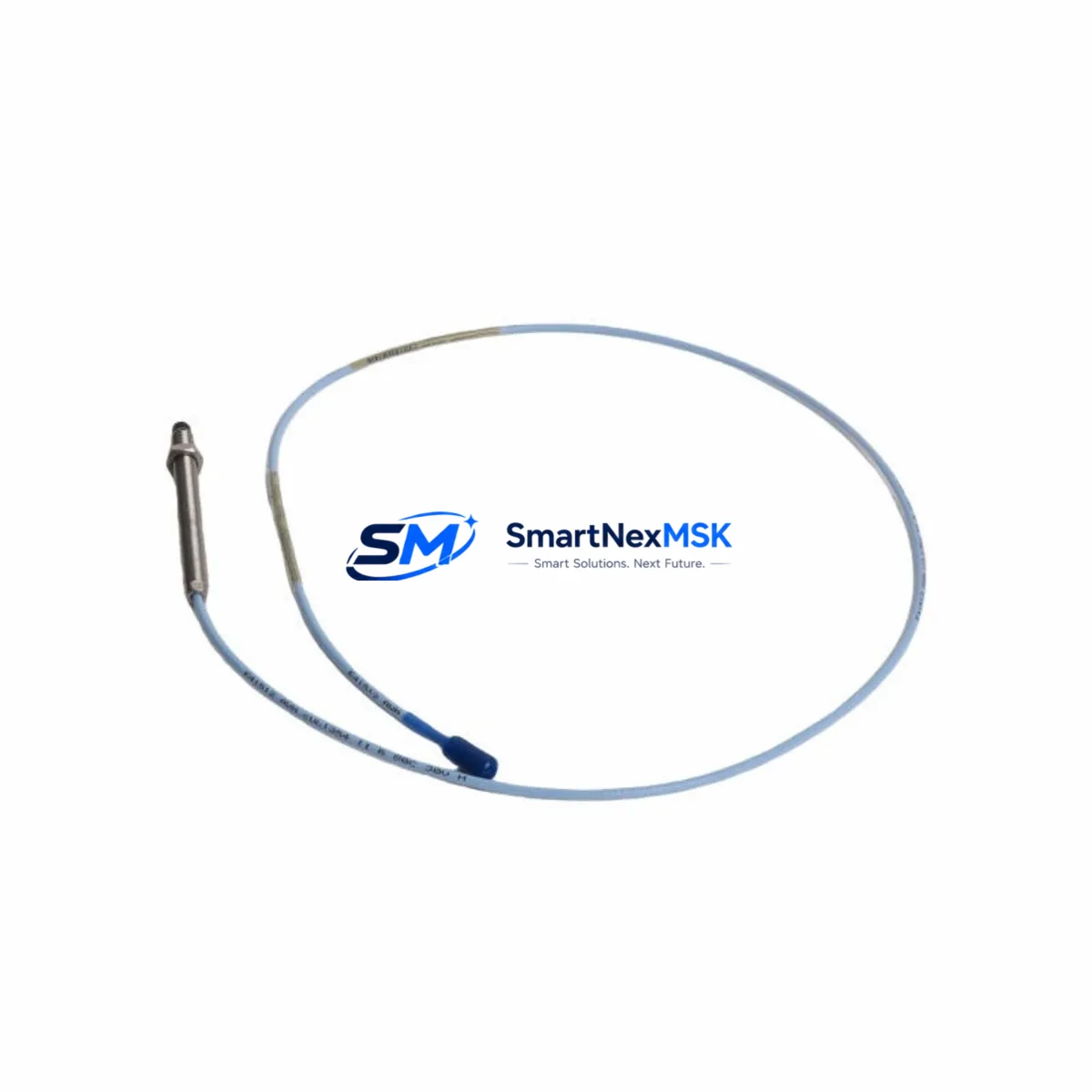
The Bently Nevada 330103-00-20-10-02-CN is an 8mm proximity probe engineered for the 3300 XL Proximity Transducer System — one of the most widely deployed vibration monitoring platforms in rotating machinery applications worldwide. As legacy installations age and OEM support windows close, this probe serves as a verified drop-in replacement for facilities managing turbines, compressors, pumps, and gearboxes that rely on continuous shaft vibration and position monitoring. Whether you are executing a planned control system upgrade, responding to an unplanned probe failure, or consolidating spare parts inventory ahead of a scheduled outage, the 330103-00-20-10-02-CN delivers the dimensional accuracy, gap voltage linearity, and CN connector interface required for seamless integration into existing 3300 XL monitor racks without reprogramming or recalibration of the monitoring system.
This probe is designed to work within the complete 3300 XL transducer chain. In a standard installation, the probe pairs with a 330130 extension cable and a 330180 proximitor sensor to deliver a calibrated output signal to the 3300/16 or 3300/20 monitor modules housed in the 3300 rack. When replacing a failed probe in the field, engineers must verify that the existing extension cable length matches the replacement probe’s calibrated system length — typically 5 or 9 meters total — since the proximitor sensor’s output sensitivity is calibrated to the combined cable and probe assembly. Mismatched cable lengths will introduce gap voltage errors and trigger false alarms or missed trips in the vibration monitor.
For facilities transitioning from older Bently Nevada 7200 Series or 3300/05 proximity systems to the current 3300 XL platform, the 330103-00-20-10-02-CN is a key component in the migration path. The 8mm probe tip diameter and -18 VDC supply voltage are consistent across the 3300 XL family, allowing the probe to be installed in existing probe holders and conduit runs without mechanical modification. However, engineers should confirm that the target material factor of the shaft — typically AISI 4140 steel — matches the probe’s calibration standard, as alternative shaft materials such as Inconel or titanium alloys require a material correction factor applied at the proximitor or monitor level.
Upgrade Compatibility Table
| Parameter | 330103-00-20-10-02-CN (This Unit) | Legacy / Replaced Model | Notes |
|---|---|---|---|
| Probe Tip Diameter | 8 mm | 8 mm (3300/05, 7200 Series) | Direct mechanical fit; no holder modification required |
| Supply Voltage | -18 VDC (from proximitor) | -18 VDC | Compatible with 330180 and 330185 proximitor sensors |
| Connector Type | CN (Coaxial, Bently Nevada standard) | CN | Mates directly with 330130 extension cable |
| Cable / System Length | 2.0 m probe + extension to 5 m or 9 m total | Verify existing extension cable length | Total system length must match proximitor calibration |
| Output Sensitivity | 7.87 V/mm (200 mV/mil) | 7.87 V/mm | No monitor rescaling required for like-for-like swap |
| Monitor Compatibility | 3300/16, 3300/20, 3500/42 | 3300/16, 3300/20 | Also compatible with 3500 Series rack via 3500/42 module |
| Installation Requirement | Standard probe holder, 3/8-24 UNF thread | Same thread standard | Confirm probe holder thread condition before installation |
| Commissioning Check | Gap voltage: -10.0 VDC ± 0.5 V at nominal gap | Same specification | Verify with calibrated gap tool or feeler gauge at 1.0 mm |
| Warranty | 12 Months | — | Covers manufacturing defects; includes pre-shipment functional test |
Retrofit Planning for Existing Automation Systems
A successful retrofit of the 330103-00-20-10-02-CN into an operating plant begins well before the maintenance window opens. The first step is a full audit of the existing transducer chain: document the probe serial number, the 330130 extension cable part number and length, and the 330180 proximitor sensor mounting location and output wiring to the 3300 rack terminal block. In many older installations, the extension cable has been field-spliced or re-terminated, which can introduce impedance discontinuities that affect the probe’s gap voltage linearity. Replacing the extension cable with a new 330130 unit at the same time as the probe is strongly recommended to eliminate this variable.
At the rack level, the 3300/16 or 3300/20 monitor module should be inspected for alarm setpoint configuration, OK relay wiring, and Keyphasor input assignments before the probe is swapped. If the facility is also upgrading from a 3300 rack to a 3500 Series rack — using the 3500/42 Proximitor Monitor module — the channel configuration must be re-entered in the 3500 rack’s System 1 software, including the transducer scale factor, gap voltage limits, and alert/danger setpoints. The 3500 rack’s Bently Nevada TDI (Transducer Driver Interface) card must also be verified for compatibility with the 330103 probe’s output impedance.
For facilities running a DCS-integrated vibration monitoring loop — for example, connecting the 3300 rack’s 4–20 mA output to a Honeywell Experion PKS or Emerson DeltaV controller — the analog input card scaling must be confirmed against the probe’s calibrated output range. A common oversight during probe replacement is failing to update the DCS tag engineering units from the old probe’s sensitivity constant, which causes the DCS historian to log incorrect vibration amplitude values even though the 3300 monitor itself is reading correctly.
In multi-channel installations — such as a four-probe arrangement on a large centrifugal compressor monitoring X-Y vibration and axial position — replacing one probe requires re-zeroing the axial position channel and verifying that the Keyphasor signal from the 330980 Keyphasor probe is still correctly phased relative to the new probe’s installation angle. The 330980 Keyphasor probe and its associated 330930 extension cable should be inspected for wear at the same time, as Keyphasor signal degradation is a common root cause of false phase readings after a proximity probe replacement.
Where the control cabinet also houses a PLC-based safety interlock — for example, a Rockwell Automation ControlLogix or Allen-Bradley SLC 500 receiving a discrete trip signal from the 3300 monitor’s relay output — the PLC ladder logic should be placed in test mode during the probe swap to prevent a nuisance trip from propagating to the ESD system. After the new probe is installed and gap voltage is confirmed, the PLC interlock should be re-enabled and a functional trip test performed to verify end-to-end signal integrity from the probe tip to the safety relay output.
Downtime Control During System Migration
Minimizing unplanned downtime during a proximity probe replacement requires a structured pre-outage preparation protocol. Before the maintenance window, the replacement 330103-00-20-10-02-CN should be bench-tested using a Bently Nevada 330180 proximitor and a calibrated target simulator to confirm gap voltage output and OK status. This pre-shipment functional test — included with every unit supplied by SMARTNEXMSK — eliminates the risk of installing a defective probe and discovering the fault only after the machine is back online.
During the outage, the original probe’s gap voltage reading should be recorded from the 3300 monitor’s front-panel display or System 1 software before power is removed. This reference value allows the commissioning engineer to set the replacement probe to the same nominal gap without relying solely on a feeler gauge, which is particularly useful in installations where physical access to the probe holder is restricted by insulation or guarding. After installation, the gap voltage should be re-measured and compared to the reference value; a deviation of more than ±0.5 VDC indicates either a gap setting error or a probe-to-shaft material mismatch that must be resolved before the machine is restarted.
To protect the original control program logic during a parallel rack upgrade — for example, migrating from a 3300 rack to a 3500 rack while the machine remains in service on the old rack — the 3500 rack should be fully configured and tested in bypass mode before the cutover. The cutover itself should be executed channel by channel, with each channel verified for correct gap voltage, OK status, and alarm setpoint response before the next channel is transferred. This incremental approach limits the exposure window during which the machine is running with reduced vibration monitoring coverage and allows the maintenance team to roll back to the 3300 rack if an unexpected configuration issue is discovered.
Retrofit Support FAQ
Q1: Is the 330103-00-20-10-02-CN a direct replacement for the original Bently Nevada part, and will it work without recalibrating the proximitor?
Yes. The 330103-00-20-10-02-CN is manufactured to the same dimensional and electrical specifications as the original Bently Nevada part. When used with the same 330130 extension cable length and 330180 proximitor sensor, no recalibration of the proximitor is required. The probe’s output sensitivity of 7.87 V/mm (200 mV/mil) is factory-set and matches the 3300 XL system’s calibration standard. A gap voltage check at the nominal installation gap is still recommended as a commissioning verification step.
Q2: What wiring checks should be performed before installing the replacement probe?
Before installation, inspect the extension cable’s CN connector for pin damage, corrosion, or contamination. Verify that the cable shield is continuous and properly grounded at the proximitor end only — grounding the shield at both ends introduces a ground loop that degrades the probe’s signal-to-noise ratio. At the 3300 rack terminal block, confirm that the OK relay wiring and the vibration signal wiring are correctly landed on the designated terminals for the channel being replaced, as terminal block labeling errors are a common source of commissioning delays.
Q3: Can this probe be used in a 3500 Series rack alongside the existing 3300 XL installation?
Yes. The 330103-00-20-10-02-CN is compatible with the 3500/42 Proximitor Monitor module in the 3500 Series rack. The transducer scale factor and gap voltage limits must be configured in the 3500 rack’s channel configuration to match the probe’s specifications. If the 3500 rack is being used as a replacement for the 3300 rack rather than in parallel, the 3300 rack’s alarm setpoints and OK relay assignments should be documented and replicated in the 3500 configuration before the cutover.
Q4: What does the 12-month warranty cover, and what pre-shipment testing is performed?
Every 330103-00-20-10-02-CN supplied by SMARTNEXMSK undergoes a pre-shipment functional test that verifies gap voltage output, OK status, and connector integrity. The 12-month warranty covers manufacturing defects in materials and workmanship from the date of shipment. It does not cover damage resulting from incorrect installation, gap setting errors, shaft material mismatches, or use outside the probe’s specified operating temperature and vibration environment. Warranty claims are processed through SMARTNEXMSK’s technical support team at sales@smartnexmsk.com.
© 2026 SMARTNEXMSK. All rights reserved.
Original Source: https://smartnexmsk.com
Contact: sales@smartnexmsk.com | +86 18259474341


