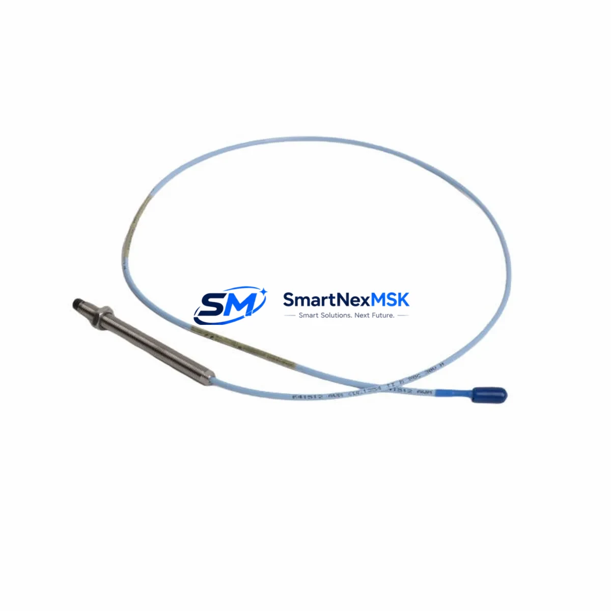
Bently Nevada 330103-00-21-10-01-00 Retrofit-Ready Proximity Transducer for 3300 XL Control Systems
The Bently Nevada 330103-00-21-10-01-00 is an 8mm proximity transducer engineered for the 3300 XL series vibration monitoring platform. As legacy Bently Nevada 3300 series components reach end-of-life or become increasingly difficult to source, this retrofit-ready replacement provides a verified drop-in solution for facilities managing rotating machinery protection systems, turbine monitoring panels, and compressor control cabinets. Whether you are executing a planned upgrade, responding to an unplanned failure, or building a critical spare inventory, the 330103-00-21-10-01-00 delivers the dimensional accuracy, signal output, and system compatibility required to restore full monitoring capability with minimal downtime.
This transducer operates within the standard Bently Nevada 3300 XL signal chain, interfacing directly with the 3300 XL proximitor/seismic monitor and the associated extension cable assemblies. The 8mm sensing tip geometry, 200 mV/mil sensitivity, and -24 VDC bias voltage output are fully consistent with the original factory specification, ensuring that existing 3500 rack systems, TDI Modbus gateway modules, and System 1 software configurations do not require recalibration upon installation. For sites running parallel monitoring loops with the 3300 XL 16-channel I/O module or the 3300 XL position monitor, the transducer integrates without firmware changes or channel remapping.
Facilities upgrading from earlier Bently Nevada 7200 series or 3000 series transducers should verify terminal block wiring compatibility at the proximitor input card before installation. The connector pinout and cable shield grounding scheme differ between generations, and incorrect wiring can introduce noise into the vibration signal chain or trigger false alerts in the 3500/42M proximity monitor module. A wiring adapter or field splice may be required when the existing extension cable — typically a 330130 series — does not match the 330103 connector standard.
Upgrade Compatibility Table
| Parameter | Detail |
|---|---|
| SKU / Part Number | 330103-00-21-10-01-00 |
| Series Compatibility | Bently Nevada 3300 XL |
| Sensing Tip Diameter | 8mm |
| Sensitivity | 200 mV/mil (7.87 V/mm) |
| Bias Voltage Output | -10.0 VDC to -18.0 VDC nominal |
| Supply Voltage | -24 VDC |
| Cable / Extension | Compatible with 330130 series extension cables |
| Proximitor Compatibility | 3300 XL Proximitor/Seismic Monitor |
| Rack Interface | 3500 series rack, 3300 XL I/O modules |
| Communication | Analog 4–20 mA / Modbus via TDI gateway |
| Replaces | 330103-00-21-10-01-00 (OEM), 7200 series (with adapter) |
| Installation Type | Direct drop-in for 3300 XL mounting brackets |
| Commissioning Note | Verify gap voltage and sensitivity at startup |
| Warranty | 12 Months from date of shipment |
Retrofit Planning for Existing Automation Systems
A successful retrofit of the 330103-00-21-10-01-00 begins well before the transducer arrives on site. Engineering teams should pull the existing loop drawing to confirm the proximitor model installed in the control cabinet — most 3300 XL installations use the 3300 XL proximitor/seismic monitor mounted directly on the machinery skid or in a nearby junction box. The proximitor’s power supply input should be verified against the plant’s -24 VDC instrument bus; if the bus voltage has drifted or the power supply module is aging, replacing the proximitor power supply card in the same maintenance window prevents a repeat outage.
Extension cable condition is a frequent source of signal degradation in aging 3300 XL systems. The 330130-08-0090 extension cable, commonly paired with 8mm transducers in this series, should be inspected for jacket damage, connector corrosion, and shield continuity before the new transducer is installed. If the cable is being replaced simultaneously, ensure the total cable length — transducer plus extension — remains within the calibrated range for the proximitor to maintain accurate gap measurement.
For facilities also upgrading their monitoring rack, the 3500/42M proximity monitor module is the recommended migration target from older 3300 XL rack cards. The 3500 rack accepts the same transducer signal format and provides enhanced diagnostics, Modbus TCP output, and compatibility with Bently Nevada System 1 condition monitoring software. If the plant HMI is running a legacy SCADA screen built around 3300 XL channel tags, the I/O tag mapping in the DCS or PLC — whether a Rockwell ControlLogix, Siemens S7-300, or Yokogawa CENTUM VP — will need to be updated to reflect the new 3500 rack channel addresses before the HMI graphics are revalidated.
Sites managing multiple machine trains should also audit their 3300 XL 16-channel I/O module assignments and confirm that the replacement transducer’s module address does not conflict with adjacent channels. Where the control system uses a Modbus gateway such as the TDI Modbus module to bridge the 3300 XL network to a plant DCS, the register map should be exported and archived before any hardware changes are made. This archive becomes the baseline for post-retrofit verification and supports faster recovery if a communication fault occurs during commissioning.
Downtime Control During System Migration
Minimizing unplanned downtime during a proximity transducer replacement requires a structured pre-outage checklist. Before isolating the measurement loop, export the current System 1 trend data and alarm setpoints for the affected machine train. This snapshot preserves the historical baseline and allows the commissioning engineer to confirm that post-installation gap voltage, direct vibration, and 1X/2X amplitude readings fall within the expected range before the machine is returned to service.
Where the process cannot tolerate a full shutdown, a temporary bypass of the affected channel in the 3500/42M monitor — using the monitor’s built-in bypass function — allows the transducer to be replaced while the remaining channels continue to protect the machine. The bypass state should be logged in the plant’s management of change system and cleared immediately after the new 330103-00-21-10-01-00 is installed and verified. Gap voltage should be set to the target value specified on the original loop calibration sheet, typically between -10.0 VDC and -18.0 VDC for an 8mm transducer at the design air gap.
After installation, a bench verification using a Bently Nevada proximitor tester or equivalent signal simulator confirms transducer output before the machine is restarted. Final commissioning should include a slow-roll check at low shaft speed to verify that the 1X reference signal is clean and that the Keyphasor input — if used for phase reference — is correctly synchronized. All findings should be documented in the site’s maintenance management system to support future reliability reviews and spare parts planning.
Retrofit Support FAQ
Q: Is the 330103-00-21-10-01-00 a direct replacement for the original Bently Nevada part?
A: Yes. This unit matches the original OEM specification for the 3300 XL 8mm proximity transducer, including sensing tip diameter, sensitivity, bias voltage, and connector type. No mechanical modification is required for standard 3300 XL mounting configurations.
Q: What wiring checks are required before installation?
A: Verify that the extension cable connector is compatible with the 330103 series, confirm shield grounding at the proximitor terminal block, and measure the -24 VDC supply voltage at the proximitor input. Incorrect supply voltage or a floating shield are the most common causes of signal noise after transducer replacement.
Q: How is compatibility with the 3500 rack confirmed?
A: The 330103-00-21-10-01-00 is compatible with the 3500/42M proximity monitor module. Confirm the channel configuration in the 3500 Rack Configuration Software matches the transducer’s sensitivity and gap range. No firmware update is required for standard 3500 rack installations.
Q: What does the 12-month warranty cover?
A: The 12-month warranty covers manufacturing defects in materials and workmanship from the date of shipment. Each unit undergoes output signal verification and dimensional inspection before dispatch. Warranty claims are supported by SMARTNEXMSK’s technical team with replacement or credit resolution within 5 business days.
© 2026 SMARTNEXMSK. All rights reserved.
Original Source: https://smartnexmsk.com
Contact: sales@smartnexmsk.com | +86 18259474341


