Bently Nevada 330103-00-24-05-02-00 Retrofit-Ready Proximity Transducer for 3300 XL Control Systems
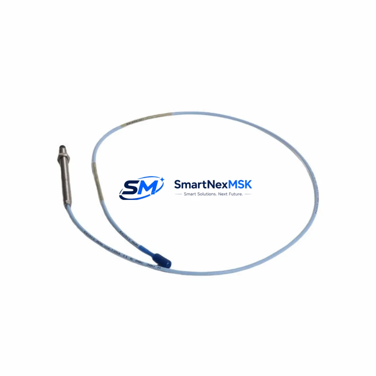
The Bently Nevada 330103-00-24-05-02-00 is a 24mm proximity transducer engineered for seamless integration into Bently Nevada 3300 XL Series vibration monitoring systems. As legacy machinery protection platforms age and OEM support windows close, this transducer serves as a verified drop-in replacement that preserves existing wiring infrastructure, signal conditioning chains, and rack-mounted monitor configurations — eliminating the need for costly full-system overhauls.
Whether you are managing a planned outage, responding to an unplanned sensor failure, or executing a phased modernization of your rotating machinery protection system, the 330103-00-24-05-02-00 delivers the dimensional accuracy, output linearity, and environmental tolerance required for continuous operation in turbines, compressors, pumps, and gearboxes across oil and gas, power generation, and petrochemical facilities.
Upgrade Compatibility Table
| Parameter | Details |
|---|---|
| SKU / Part Number | 330103-00-24-05-02-00 |
| Series Compatibility | Bently Nevada 3300 XL Vibration Monitoring System |
| Probe Diameter | 24 mm |
| Cable Length | 5 m (extension cable) |
| Output Signal | –24 VDC, eddy-current, linear range per 3300 XL spec |
| Connector Interface | Standard 3300 XL coaxial connector — no adapter required |
| Installation Requirement | Direct mount; verify gap voltage per OEM commissioning guide |
| Communication Compatibility | Compatible with 3300 XL monitors, Keyphasor modules, and System 1 software |
| Replacement Recommendation | Direct replacement for 330103-00-24-05-02-00; verify driver/extension cable pairing |
| Commissioning Focus | Gap voltage setting, polarity check, signal noise floor verification |
| Warranty | 12-Month Warranty — functional and dimensional compliance guaranteed |
Retrofit Planning for Existing Automation Systems
Successful retrofit of the 330103-00-24-05-02-00 into an operating plant begins well before the maintenance window opens. Engineers must first audit the existing 3300 XL rack configuration, confirming which monitor slots — typically housing the 3300/16 Dual Voting or 3300/20 Radial Vibration Monitor — are paired with the current transducer. The extension cable, commonly a 330130-series armored cable, must be inspected for continuity and shield integrity before reuse; a degraded cable will introduce noise that masks the transducer’s output accuracy.
Power supply capacity within the control cabinet is a critical checkpoint. The 3300 XL system draws regulated –24 VDC from a dedicated power supply module, and adding or replacing transducers without verifying available current headroom can cause voltage sag that triggers false alarms across adjacent channels. Confirm that the 3300 Power Supply module has sufficient margin before proceeding.
Terminal block wiring at the junction box must be documented and photographed prior to disconnection. The coaxial signal path — probe body to extension cable to driver — must maintain consistent impedance; substituting mismatched cable lengths will shift the linear range and require recalibration of the 3300 XL monitor’s gap voltage setpoint. After installation, use a calibrated oscilloscope or the System 1 software interface to verify the –12 VDC nominal gap voltage and confirm the transducer is operating within its linear range before returning the machine to service.
For facilities running parallel Keyphasor signals for phase reference, ensure the 330180-series Keyphasor transducer on the same shaft is also inspected during the same outage window — replacing one sensor while leaving an aged Keyphasor in place is a common source of post-retrofit phase measurement errors. Similarly, if the plant is migrating from a legacy 3300 Series rack to a newer System 1 Evolution platform, the 330103-00-24-05-02-00 remains compatible with both architectures, simplifying the transition and protecting the capital investment in existing field wiring.
I/O channel mapping in the DCS or safety system should be verified against the updated tag database. If the transducer feeds a voted shutdown logic (2oo3 or 1oo2), confirm that the voting configuration in the 3300/16 monitor is correctly set and that the bypass switch is engaged during commissioning to prevent spurious trips. After gap voltage verification, release the bypass and perform a functional trip test before closing the maintenance work order.
Downtime Control During System Migration
Minimizing unplanned downtime during a proximity transducer replacement requires a structured pre-outage preparation protocol. Before the maintenance window, stage the 330103-00-24-05-02-00 alongside the required extension cable, connector tools, and a calibrated gap-setting tool. Pre-configure the replacement transducer’s expected gap voltage in the System 1 software so that post-installation verification is a confirmation step rather than a diagnostic exercise.
Where plant operations permit, use the 3300 XL monitor’s channel bypass function to isolate the affected measurement point without shutting down adjacent channels. This preserves vibration monitoring continuity on the remaining channels of the same rack — critical for machines that cannot be taken fully offline. Document the original program logic, alarm setpoints, and danger thresholds from the 3300 XL monitor before any hardware change; these values must be restored and verified after the new transducer is commissioned.
For facilities with System 1 software historian integration, confirm that the data tag associated with the replaced transducer channel is re-mapped correctly after commissioning. A mismapped tag will silently log incorrect vibration data, creating compliance and reliability risks. Perform a 30-minute post-commissioning observation period with the machine at operating speed before declaring the retrofit complete, confirming that vibration amplitude, phase, and gap voltage readings are stable and within alarm margins.
Retrofit Support FAQ
Q: Is the 330103-00-24-05-02-00 a direct replacement for the original Bently Nevada part?
A: Yes. This unit is manufactured to the same dimensional and electrical specifications as the original 330103-00-24-05-02-00. It is compatible with the 3300 XL monitor rack, existing extension cables, and System 1 software without modification.
Q: What commissioning steps are required after installation?
A: After mechanical installation, set the probe gap to achieve the nominal –12 VDC output using a calibrated gap tool. Verify signal linearity through the 3300 XL monitor display or System 1 software. Confirm alarm and danger setpoints are correctly restored before releasing the channel from bypass.
Q: Can this transducer be used with both armored and non-armored extension cables?
A: Yes, provided the extension cable is a compatible 330130-series or equivalent with matching impedance. Always verify total cable length against the driver’s specified linear range to avoid calibration offset.
Q: What does the 12-month warranty cover?
A: The 12-month warranty covers functional performance, dimensional compliance, and connector integrity under normal operating conditions. Each unit undergoes pre-shipment functional testing. Warranty claims are supported directly through our sales team.
© 2026 SMARTNEXMSK. All rights reserved.
Original Source: https://smartnexmsk.com
Contact: sales@smartnexmsk.com | +86 18259474341


