Bently Nevada 330103-00-24-10-02-00 Maintenance-Ready Spare for 3300 XL Automation
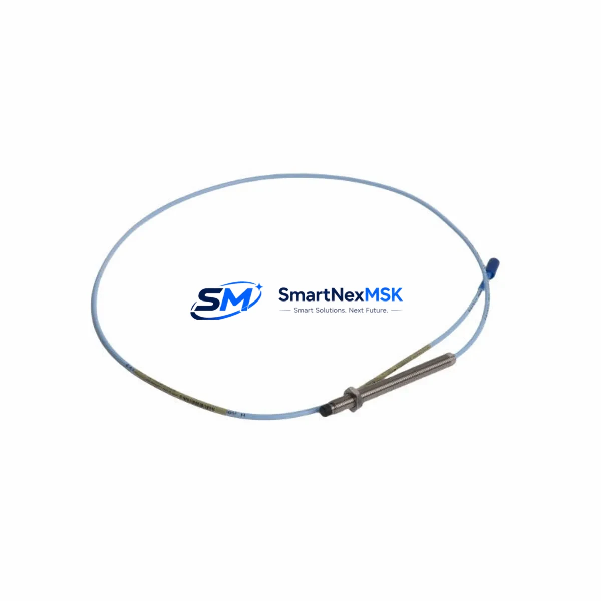
The Bently Nevada 330103-00-24-10-02-00 is an original proximity transducer system designed for continuous vibration monitoring in rotating machinery applications. As a critical component within the 3300 XL Series condition monitoring platform, this transducer provides non-contact displacement measurement essential for detecting shaft vibration, radial position, and axial thrust in turbines, compressors, pumps, and motors operating in demanding industrial environments.
For maintenance engineers managing aging DCS or PLC-integrated monitoring systems, having a verified spare of the 330103-00-24-10-02-00 on hand is a fundamental risk-reduction strategy. Unplanned downtime caused by transducer failure in a critical rotating asset can cascade into production losses far exceeding the cost of a stocked spare. This unit ships fully tested, with electrical continuity and output signal verified prior to dispatch, and is backed by a 12-month warranty covering manufacturing defects and performance conformance.
Procurement engineers sourcing replacement parts for Bently Nevada 3300 XL systems will find this SKU directly interchangeable with the original factory-installed unit. Compatibility has been validated against the 3300 XL monitor rack architecture, including standard 3300/16 and 3300/20 monitor cards. The transducer operates within the standard Bently Nevada eddy-current sensing chain, requiring no firmware changes or recalibration of the monitor card when replacing a like-for-like unit.
Spare Maintenance Table
| Parameter | Specification |
|---|---|
| Part Number | 330103-00-24-10-02-00 |
| Brand | Bently Nevada |
| Series | 3300 XL Proximity Transducer System |
| Sensing Technology | Eddy-Current (Non-Contact) |
| Cable Length | 24 inches (integral cable) |
| Thread Size | 10-32 UNF |
| Tip Diameter | 8 mm |
| Linear Range | 0.25 mm – 2.25 mm (nominal) |
| Output Sensitivity | -7.87 V/mm (nominal) |
| Supply Voltage | -24 VDC (via Proximitor/Seismic Monitor) |
| Operating Temperature | -35°C to +120°C |
| Target Material Compatibility | AISI 4140 steel (standard); verify for non-ferrous shafts |
| Connector Type | 2-pin MIL-C-5015 (integral) |
| Compatible Monitor Cards | 3300/16, 3300/20, 3300 XL series |
| Compatible Proximitor | 3300 XL 8mm Proximitor Sensor |
| Installation Environment | Hazardous area rated; suitable for Zone 1/Division 1 |
| Condition | Original, tested before shipment |
| Warranty | 12 Months |
| Origin | United States |
Maintenance Planning for Continuous Operation
When replacing the 330103-00-24-10-02-00 transducer during a planned outage or emergency callout, a thorough inspection of the surrounding sensing chain and monitor infrastructure is essential to prevent repeat failures and ensure measurement integrity after recommissioning.
Begin with the 3300 XL 8mm Proximitor Sensor (typically mounted in the junction box or field enclosure). The Proximitor converts the transducer’s impedance change into a voltage signal; a degraded or moisture-contaminated Proximitor will produce erratic readings even with a new transducer installed. Inspect the Proximitor’s output voltage at the monitor card input terminals and verify it falls within the –24 VDC supply window.
Check the extension cable assembly connecting the transducer to the Proximitor. Bently Nevada extension cables are impedance-matched to the transducer and Proximitor combination; substituting a non-matched cable will shift the linear range and introduce measurement error. Inspect the cable jacket for abrasion, heat damage, or crush points common in rotating machinery enclosures.
At the 3300/16 or 3300/20 monitor card level, verify that the OK relay output is healthy and that the channel is not latched in a fault state from the previous transducer failure. A latched OK relay may prevent the new transducer from being recognized even after correct installation. Clear any latched alarms via the 3300 System Monitor or the associated Rack Interface Module (RIM) before returning the channel to service.
Inspect the -24 VDC power supply module feeding the monitor rack. Voltage sag or ripple on the DC bus is a common root cause of transducer system instability and can accelerate wear on replacement units. Use a calibrated multimeter to confirm supply voltage at the rack backplane terminals.
For systems integrated with a DCS or safety PLC via 4–20 mA or Modbus RTU output from the 3300 monitor, verify that the analog output card and signal conditioning module are reading correctly after transducer replacement. A signal isolator between the monitor output and the DCS analog input card protects against ground loops that can corrupt vibration data.
If the control cabinet houses a Bently Nevada 3500 series rack alongside the 3300 XL system, cross-check that the 3500/42M Proximitor I/O Module or 3500/25 keyphasor module are not generating spurious alerts that could be misattributed to the replaced transducer channel. Review the System 1 Evolution software trend data for the 48 hours preceding the failure to distinguish transducer degradation from process-driven vibration changes.
Finally, confirm that the terminal strip and field wiring in the junction box are clean, torqued to specification, and free of corrosion. Loose or oxidized terminals are a frequent cause of intermittent OK dropouts that mimic transducer failure and can lead to unnecessary part replacement.
Site Replacement Workflow
Step 1 – Isolation and Permit: Obtain a work permit and isolate the monitor channel at the 3300 XL rack. Place the channel in bypass mode to prevent spurious shutdown signals to the machinery protection system during the swap.
Step 2 – Transducer Removal: Loosen the locknut and unscrew the 330103-00-24-10-02-00 from the probe holder. Note the gap voltage reading (typically –10 VDC at nominal gap) before disconnection for reference during reinstallation.
Step 3 – Gap Setting: Thread the replacement transducer into the probe holder and adjust the gap to achieve the nominal –10 VDC output (corresponding to approximately 1.0 mm gap for 8 mm tip on AISI 4140 target). Use a non-metallic feeler gauge or the Proximitor output voltage as the reference. Tighten the locknut to the specified torque.
Step 4 – Signal Verification: With the machine at rest, confirm the Proximitor output voltage is within the linear range. Check the monitor card for a healthy OK status and verify that the gap alarm setpoints are not exceeded.
Step 5 – Return to Service: Remove the channel bypass, confirm the OK relay is energized, and monitor the vibration trend for the first 30 minutes of machine operation. Document the replacement in the maintenance management system with the new part serial number and gap voltage recorded.
This workflow minimizes downtime to under two hours for a trained technician and eliminates the risk of incorrect gap setting that can cause immediate re-failure of the replacement unit.
Spare Parts Support FAQ
Q: Is the 330103-00-24-10-02-00 a direct drop-in replacement for older 330103 series transducers?
A: Yes. The 330103-00-24-10-02-00 is backward-compatible with the 3300 XL sensing chain and is interchangeable with earlier 330103 variants provided the cable length, thread size, and tip diameter match the probe holder specification. Always verify the Proximitor model is rated for the 8 mm tip series before installation.
Q: What pre-shipment testing is performed on this unit?
A: Each unit undergoes electrical continuity testing, insulation resistance verification, and output voltage calibration check against a reference target before dispatch. A test report is available upon request. Units that do not meet Bently Nevada OEM performance specifications are not shipped.
Q: How should this spare be stored to maintain its service life?
A: Store in the original packaging or an anti-static bag in a dry environment between –20°C and +60°C, away from strong magnetic fields and mechanical shock. Inspect the cable jacket and connector pins annually. Recommended maximum shelf life before in-service inspection is 5 years.
Q: What is covered under the 12-month warranty?
A: The 12-month warranty covers manufacturing defects, electrical performance non-conformance, and premature failure under normal operating conditions. It does not cover damage resulting from incorrect gap setting, mechanical impact, chemical exposure, or installation in an incompatible sensing chain. Warranty claims are processed within 5 business days of receipt of the returned unit.
© 2026 SMARTNEXMSK. All rights reserved.
Original Source: https://smartnexmsk.com
Contact: sales@smartnexmsk.com | +86 18259474341


