Bently Nevada 330103-00-25-10-01-CN 3300 XL Maintenance-Ready Spare for 3300 XL Automation
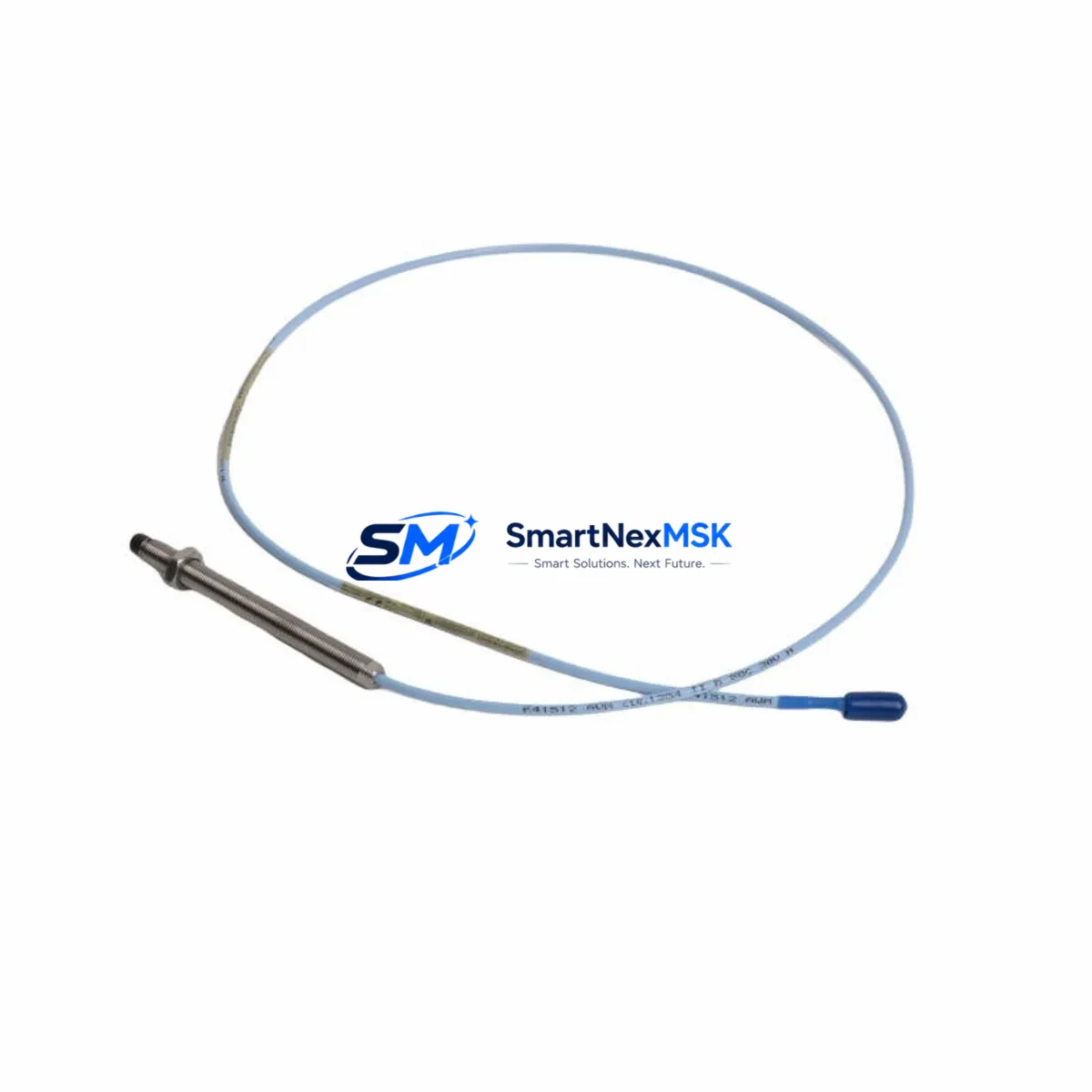
The Bently Nevada 330103-00-25-10-01-CN is an original eddy-current proximity transducer engineered for the 3300 XL Series continuous machinery monitoring system. Designed for critical rotating equipment — including steam turbines, gas compressors, centrifugal pumps, and large induction motors — this transducer delivers precise radial shaft vibration and position measurements essential for condition-based maintenance programs. Sourced as a genuine original spare, each unit is individually tested prior to shipment and backed by a 12-month warranty, ensuring your maintenance team can restore system integrity with confidence and minimal downtime.
For maintenance engineers managing aging turbomachinery or DCS-integrated monitoring racks, having a verified replacement of the 330103-00-25-10-01-CN on the shelf is a fundamental risk-reduction strategy. Unplanned transducer failure in a 3300 XL rack can trigger false shutdowns, mask real vibration anomalies, or leave critical machinery running unprotected. Stocking this spare eliminates the lead-time risk associated with OEM procurement channels and supports rapid fault isolation during scheduled outages or emergency callouts.
Spare Maintenance Table
| Parameter | Specification |
|---|---|
| Part Number | 330103-00-25-10-01-CN |
| Brand | Bently Nevada |
| Series | 3300 XL |
| Sensor Type | Eddy-Current Proximity Transducer |
| Cable Length | 25 ft (7.62 m) integral cable |
| Thread Size | 10-32 UNF (standard 3300 XL mount) |
| Tip Diameter | 8 mm |
| Operating Voltage | -24 VDC (nominal, via Proximitor) |
| Output Signal | -2 VDC to -18 VDC linear range |
| Sensitivity | 200 mV/mil (7.87 V/mm) |
| Linear Range | 80 mil (2.03 mm) |
| Target Material Compatibility | AISI 4140 steel (standard); verify for non-ferrous targets |
| Operating Temperature | -35°C to +177°C (probe tip) |
| Environmental Rating | IP67 (connector end sealed) |
| Compatible Proximitor | 3300 XL 8mm Proximitor Sensor (e.g. 330180-X1-05) |
| Compatible Monitor | 3300/16 Dual Voting, 3500/42 Proximitor/Seismic Monitor |
| Application | Radial vibration, axial position, differential expansion |
| Origin | USA |
| Warranty | 12 Months from date of shipment |
| Pre-shipment Test | Functional output verification, cable continuity, insulation check |
Maintenance Planning for Continuous Operation
When replacing the 330103-00-25-10-01-CN in the field, a disciplined maintenance engineer will treat the transducer swap as an opportunity to audit the entire measurement chain. The 3300 XL proximity system is a three-component assembly: the probe, the extension cable, and the Proximitor sensor. Replacing only the probe while leaving a degraded 3300 XL extension cable (such as the 330130-080-00-00) in place is a common source of post-replacement signal drift. Always perform a cable continuity and shield integrity check before re-commissioning.
The 3300 XL 8mm Proximitor Sensor (typically the 330180 series) should be inspected for output voltage stability at the nominal gap. If the Proximitor output is outside the -10 VDC ±0.5 VDC window at the standard 50-mil gap, replace the Proximitor as a matched set with the new probe. In 3500 Series rack installations, verify that the 3500/42 Proximitor/Seismic Monitor channel configuration — including OK limits, full-scale range, and transducer type selection — matches the replacement transducer’s sensitivity curve.
Procurement engineers should also review the status of associated 3500/01 Rack Interface Module and 3500/20 Rack Interface I/O Module firmware versions, as outdated firmware can cause transducer OK channel misreads after hardware replacement. For installations where the 3300 XL rack feeds a DCS or safety system, confirm that the 4–20 mA output isolator or signal conditioner downstream of the monitor is within calibration — a faulty isolator can mask a healthy transducer reading at the control room level.
In control cabinet inspections, check the terminal blocks and field wiring connecting the Proximitor to the monitor card. Loose or corroded terminals on the coaxial signal path are a frequent root cause of intermittent OK trips that are incorrectly attributed to transducer failure. Additionally, inspect the cabinet power supply rail supplying -24 VDC to the Proximitor; voltage sag below -22 VDC will shift the transducer’s linear range and produce false vibration readings. For legacy systems approaching end-of-life, consider stocking a 3300 XL Proximitor Sensor and a spare 3500 Series power supply module alongside the 330103-00-25-10-01-CN to support a complete measurement loop restoration without additional procurement delays.
Site Replacement Workflow
Step 1 — Pre-shutdown verification: Confirm the existing transducer’s gap voltage and OK status via the 3500 rack front panel or DCS historian. Document the baseline reading for post-installation comparison.
Step 2 — Isolation and removal: Isolate the monitor channel (bypass or inhibit the OK output to prevent spurious trips during replacement). Disconnect the coaxial connector at the Proximitor, then unthread the probe from the bearing housing bracket using the correct spanner. Avoid bending the integral cable during extraction.
Step 3 — Installation of 330103-00-25-10-01-CN: Thread the replacement probe to the specified torque (typically 20–25 in-lb for 10-32 UNF). Set the initial gap to 50 mil (1.27 mm) using a non-ferrous feeler gauge or gap-setting tool. Reconnect the coaxial cable to the Proximitor.
Step 4 — Commissioning check: Restore power and verify Proximitor output voltage at the set gap. Confirm the monitor channel returns to OK status and that the vibration reading is within the expected baseline range (±10% of pre-shutdown value). Remove the bypass/inhibit.
Step 5 — Documentation: Record the replacement date, new gap setting, output voltage, and technician ID in the equipment maintenance log. Update the spare parts inventory to trigger reorder of the consumed unit.
This workflow is compatible with both planned outage windows and emergency callout scenarios, and has been validated for use with 3300 XL and 3500 Series monitor racks without requiring system reconfiguration when replacing a like-for-like 330103-series transducer.
Spare Parts Support FAQ
Q1: Is the 330103-00-25-10-01-CN compatible with both 3300 XL and 3500 Series monitor racks?
Yes. The 330103-00-25-10-01-CN is a standard 3300 XL 8mm eddy-current probe and is fully compatible with any 3300 XL Proximitor Sensor and 3500 Series monitor card configured for 8mm transducer input. No channel reconfiguration is required when replacing a like-for-like unit. Always verify the monitor’s transducer type setting matches the 200 mV/mil sensitivity before re-commissioning.
Q2: How do you verify the replacement unit before installation?
Each 330103-00-25-10-01-CN shipped from our inventory undergoes pre-shipment functional testing: output voltage sweep across the linear range, cable continuity, shield-to-conductor insulation resistance, and connector integrity. A test report is available upon request. On-site, perform a bench gap test using a calibrated Proximitor and target block before installing in the bearing housing.
Q3: What is the recommended spare parts stocking strategy for 3300 XL proximity systems?
For critical rotating equipment (turbines, compressors), maintain a minimum of one probe, one extension cable, and one Proximitor sensor per monitored bearing as on-shelf spares. For non-critical equipment, a shared pool of two probe sets per site is typically sufficient. Given the 12-month warranty on each unit, rotate stock annually to ensure all spares remain within warranty coverage at the time of use.
Q4: What is the warranty coverage and what does it include?
All units carry a 12-month warranty from the date of shipment. Coverage includes manufacturing defects, output calibration drift beyond specification, and cable/connector integrity failures under normal operating conditions. Warranty claims are processed with a replacement unit dispatched within 5 business days upon receipt of the returned item and fault confirmation. Physical damage from improper installation or over-torquing is excluded from coverage.
© 2026 SMARTNEXMSK. All rights reserved.
Original Source: https://smartnexmsk.com
Contact: sales@smartnexmsk.com | +86 18259474341


