Bently Nevada 330103-00-25-10-02-CN Spare 3300 XL: Precision Spare for Vibration Monitoring Continuity
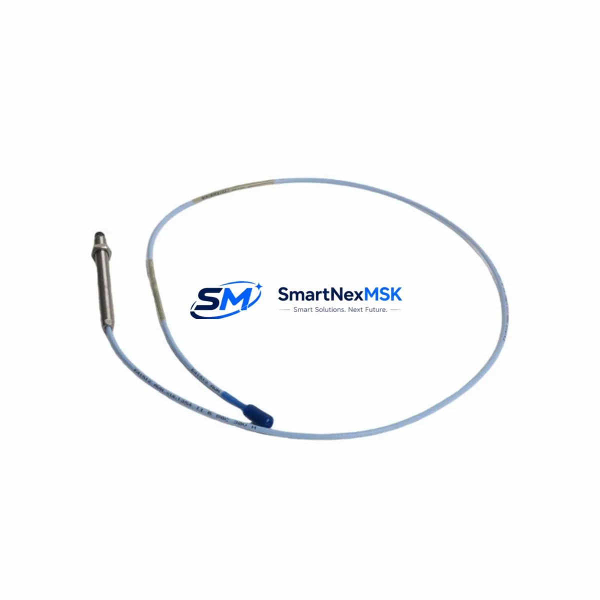
The Bently Nevada 330103-00-25-10-02-CN is a 25 mm range proximity transducer forming part of the 3300 XL Series Proximity Transducer System — one of the most widely deployed eddy-current sensing platforms in rotating machinery protection worldwide. Designed for continuous shaft vibration, position, and eccentricity measurement, this transducer is a critical field-replaceable unit in turbines, compressors, pumps, gearboxes, and motor-driven equipment across oil and gas, power generation, petrochemical, and heavy manufacturing facilities.
For maintenance engineers and spare parts procurement teams managing aging machinery protection systems, maintaining a verified stock of the 330103-00-25-10-02-CN is a fundamental risk-control measure. Unplanned transducer failure — whether from cable damage, probe tip wear, environmental contamination, or connector corrosion — can trigger a machinery trip, force an unplanned shutdown, and expose rotating equipment to undetected mechanical faults. Having a tested, ready-to-install spare on the shelf is the single most effective way to compress mean time to repair (MTTR) and restore protection coverage within a single maintenance shift.
The “-CN” suffix designation on this part number indicates a specific cable length and connector configuration optimized for installations where the transducer-to-driver cable routing requires a defined extension. When sourcing a replacement, it is essential to confirm that the replacement unit carries the identical full part number — including the “-CN” suffix — to ensure dimensional, electrical, and mechanical compatibility with the installed 3300 XL driver, typically the 330180 Series proximitor/driver module mounted in the field junction box or control cabinet.
Spare Maintenance Table
| Parameter | Specification / Recommendation |
|---|---|
| Part Number | 330103-00-25-10-02-CN |
| Brand | Bently Nevada |
| Series | 3300 XL Proximity Transducer System |
| Sensing Range | 25 mm (nominal linear range) |
| Probe Diameter | 8 mm (standard) |
| Cable Length | Per “-CN” configuration (confirm against installed routing) |
| Output Sensitivity | 7.87 V/mm (200 mV/mil) nominal |
| Supply Voltage | -24 VDC (via 330180 proximitor driver) |
| Operating Temperature | -35°C to +120°C (probe tip) |
| Compatibility | 3300 XL Series drivers, 3500 Series rack (with adapter), System 1 software |
| Installation | Threaded probe mount; confirm gap voltage at installation (typically -10 to -18 VDC) |
| Application | Radial vibration, axial position, differential expansion, eccentricity |
| Maintenance Interval | Inspect annually or per OEM PM schedule; replace on gap voltage drift or cable damage |
| Warranty | 12-Month Warranty — tested prior to shipment |
Maintenance Planning for Continuous Operation
Effective maintenance planning for a 3300 XL-based machinery protection system extends well beyond the transducer itself. When a 330103-00-25-10-02-CN is flagged for replacement during a scheduled outage or emergency callout, the maintenance team should treat the event as an opportunity to inspect the entire measurement chain and associated cabinet components.
Begin with the 330180 Series proximitor/driver module — the signal conditioning unit that powers the transducer and converts the raw eddy-current signal to a usable voltage output. A degraded driver can produce erratic gap readings even with a new probe installed. Verify the driver’s output voltage and confirm it falls within the calibrated range before closing out the work order.
Inspect the 330130 extension cable connecting the probe to the driver. Extension cables are a common failure point in high-vibration or high-temperature environments; look for jacket cracking, connector pin corrosion, and continuity loss. A new transducer paired with a compromised extension cable will not restore measurement accuracy.
Within the control cabinet, check the 3300 XL monitor card (such as the 3300/16 or 3300/20 series) for alarm setpoint integrity and relay output function. Confirm that the 3500/42M Proximitor/Seismic Monitor — if the system has been partially upgraded to the 3500 platform — is correctly configured to accept the 3300 XL transducer signal range. Mismatched sensitivity settings between the transducer and monitor card are a leading cause of nuisance trips after spare part replacement.
Review the 3500/15 Power Supply module supplying the rack. Aging power supplies with marginal output regulation can introduce noise into the -24 VDC transducer supply rail, causing baseline gap voltage instability. If the power supply has not been replaced within its recommended service life, include it in the maintenance scope.
For facilities running System 1 Evolution condition monitoring software, confirm that the channel configuration database reflects the new transducer’s calibration data and that historical trend baselines are preserved. If the installation uses a TDXnet data acquisition module or a 3500/92 Communication Gateway for Modbus or OPC integration to the DCS or SCADA layer, verify that the communication link remains active and that the channel tag mapping is intact after the replacement.
Finally, inspect the terminal blocks and grounding bars within the junction box and control cabinet. Loose terminations on the signal common or shield drain wire are a frequent source of high-frequency noise on proximity channels. Torque all terminals to specification and confirm shield continuity from probe tip to the monitor card’s signal reference ground.
Site Replacement Workflow
A structured on-site replacement workflow for the 330103-00-25-10-02-CN minimizes downtime and reduces the risk of introducing new faults during the maintenance intervention:
Step 1 — Pre-replacement verification: Confirm the full part number of the installed transducer against the maintenance record. Photograph the existing probe installation, noting the gap distance, mounting thread engagement, and cable routing. Record the current gap voltage from the monitor display or System 1 trend screen as a baseline reference.
Step 2 — Isolation and removal: Follow the site’s lock-out/tag-out (LOTO) procedure for the measurement channel. Disconnect the extension cable at the junction box connector. Unthread the probe from the mounting bracket, taking care not to damage the probe tip or the target shaft surface.
Step 3 — New unit installation: Install the replacement 330103-00-25-10-02-CN to the same thread engagement depth as the original. Reconnect the extension cable. Restore power to the channel and allow the system to stabilize for a minimum of 5 minutes before reading the gap voltage.
Step 4 — Gap setting and calibration check: Adjust the probe gap to achieve a gap voltage within the linear range specified for the installed driver (typically -10 to -18 VDC for a 3300 XL system). Compare the new gap voltage to the pre-removal baseline. A significant deviation may indicate a shaft surface condition change or a driver calibration issue requiring further investigation.
Step 5 — Functional test and documentation: Confirm alarm and danger setpoints are active on the monitor card. Verify relay output function by simulating an over-limit condition if the site procedure permits. Update the maintenance record with the new transducer serial number, installation date, and measured gap voltage. All units supplied by SMARTNEXMSK are tested prior to shipment and covered by a 12-month warranty.
Spare Parts Support FAQ
Q1: Is the 330103-00-25-10-02-CN a direct drop-in replacement for other 330103 variants?
The 330103 family shares the same 8 mm probe body and 3300 XL electrical interface, but cable length and connector configurations differ by suffix. The “-CN” designation specifies a particular cable length and termination style. Always confirm the full part number — including all suffix segments — matches the installed unit before ordering. Substituting a different suffix may require re-routing the extension cable or changing the junction box connector.
Q2: How should I manage spare inventory for a fleet of 3300 XL transducers?
For facilities with 10 or more installed 3300 XL channels, a minimum stock of 2–3 units per transducer variant is recommended. Transducers in high-vibration or high-temperature zones should be inspected at every planned outage and replaced proactively if gap voltage drift exceeds ±1 VDC from the original calibrated baseline. Maintaining a documented spare parts register with part numbers, quantities, and last-inspection dates reduces emergency procurement lead times significantly.
Q3: What pre-shipment testing is performed on the 330103-00-25-10-02-CN?
All units supplied by SMARTNEXMSK undergo electrical continuity verification, insulation resistance testing, and functional output sensitivity checks against the Bently Nevada 3300 XL specification prior to shipment. A test report is available upon request. Units are packaged in anti-static, shock-protected packaging to prevent transit damage. The 12-month warranty covers manufacturing defects and verified electrical failures under normal operating conditions.
Q4: Can this transducer be used with the Bently Nevada 3500 Series monitoring system?
The 330103-00-25-10-02-CN is natively compatible with the 3300 XL driver/proximitor ecosystem. It can be used with the 3500 Series platform when paired with a compatible 3500 Series proximitor monitor card (such as the 3500/42M) configured for the 3300 XL transducer sensitivity range (7.87 V/mm). Confirm the monitor card’s input configuration and gap voltage acceptance range before installation in a 3500 rack to avoid calibration errors or nuisance trips.
© 2026 SMARTNEXMSK. All rights reserved.
Original Source: https://smartnexmsk.com
Contact: sales@smartnexmsk.com | +86 18259474341


