Bently Nevada 330103-02-08-10-02-00 Retrofit-Ready Proximity Transducer for 3300 XL Control Systems
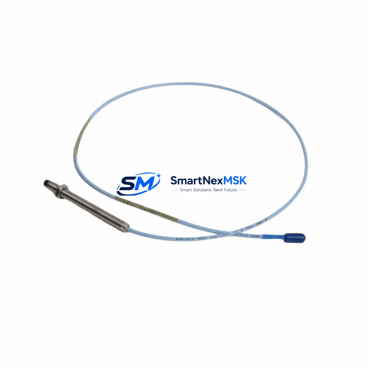
The Bently Nevada 330103-02-08-10-02-00 is an 8mm eddy-current proximity transducer engineered for the 3300 XL Series continuous machinery monitoring platform. As legacy vibration monitoring systems age out of OEM support cycles, this unit serves as a direct retrofit solution for facilities operating rotating machinery — including steam turbines, gas compressors, centrifugal pumps, and large induction motors — where unplanned downtime carries significant operational and financial risk.
This transducer is designed to integrate seamlessly into existing 3300 XL monitor racks without requiring panel re-engineering. Its 8mm tip diameter, standard Bently Nevada extension cable interface, and calibrated sensitivity of 7.87 V/mm (200 mV/mil) ensure compatibility with the signal conditioning chain already installed in your control cabinet. When replacing a failed or end-of-life unit, engineers should verify the existing Bently Nevada 330130 extension cable length and confirm that the 3300 XL monitor channel — such as the 3300/16 or 3300/20 dual-channel monitor — is configured for the correct gap voltage range, typically –10 VDC at the calibrated gap of 1.0 mm (40 mil).
For facilities running Baker Hughes / Bently Nevada System 1 software or the legacy ADRE 408 DSPi data acquisition platform, the 330103-02-08-10-02-00 requires no firmware changes or recalibration of the monitoring software. The transducer’s output is fully compatible with existing trend and alarm setpoints stored in the System 1 database, preserving years of baseline vibration data and alarm logic without modification.
Upgrade Compatibility Table
| Parameter | Detail |
|---|---|
| SKU / Part Number | 330103-02-08-10-02-00 |
| Series Compatibility | Bently Nevada 3300 XL Series |
| Tip Diameter | 8 mm |
| Sensitivity | 7.87 V/mm (200 mV/mil) |
| Calibrated Gap | 1.0 mm (40 mil) @ –10 VDC |
| Linear Range | 0.25 – 2.25 mm (10 – 90 mil) |
| Supply Voltage | –24 VDC (nominal) |
| Extension Cable Interface | Bently Nevada 330130 Series (standard) |
| Monitor Compatibility | 3300/16, 3300/20, 3300/25, 3300/46, 3300/55 |
| Installation Type | Drop-in replacement, no panel re-engineering required |
| Communication Protocol | Analog 4–20 mA / voltage output; compatible with System 1 and ADRE 408 |
| Retrofit Recommendation | Direct replacement for 330103-02-08-10-02-00; verify gap voltage and cable length before commissioning |
| Commissioning Note | Confirm channel gap voltage at –10 VDC; re-zero OK button in monitor after installation |
| Warranty | 12 Months from date of shipment |
Retrofit Planning for Existing Automation Systems
A successful retrofit of the 330103-02-08-10-02-00 begins well before the transducer arrives on site. Maintenance engineers should audit the full measurement chain: the transducer itself, the 330130 extension cable (available in 1m, 3m, 5m, and 9m lengths), and the Bently Nevada 3300 XL proximitor / driver. The proximitor — typically a 330180 or 330185 series unit — conditions the raw eddy-current signal and must be confirmed operational before attributing a fault to the transducer. If the proximitor is also suspect, replacing both components simultaneously during a planned outage is strongly recommended to avoid a second shutdown.
Inside the control cabinet, verify that the terminal block wiring follows the Bently Nevada standard color code: the coaxial cable center conductor connects to the negative input terminal, and the shield connects to the common terminal. Incorrect polarity will produce an out-of-range gap voltage and trigger a Not OK status on the 3300/16 or 3300/20 monitor card. If the facility uses a Bently Nevada 3300/05 power supply module to feed the monitoring rack, confirm that the –24 VDC rail is within specification (–21 to –26 VDC) before energizing the new transducer.
For plants migrating from older Bently Nevada 7200 Series or 3300 (non-XL) monitors to the 3300 XL platform, the 330103-02-08-10-02-00 is the correct transducer for the new system. However, the legacy 7200 Series proximitor is not compatible with 3300 XL monitors; the 330180 proximitor must be installed as part of the upgrade. Additionally, if the facility’s DCS — such as a Honeywell Experion PKS, Emerson DeltaV, or ABB System 800xA — receives vibration data via a 4–20 mA hardwired input from the 3300 XL monitor, verify that the DCS analog input card scaling matches the new monitor’s output range to avoid false alarms or missed trips.
Plants using a Bently Nevada 3500 Series rack for API 670-compliant machinery protection should note that the 330103-02-08-10-02-00 is also compatible with 3500/42M and 3500/45 monitor modules, making it a versatile stocking item for facilities that operate both 3300 XL and 3500 Series platforms. Keeping a small buffer stock of this transducer, along with the 330130 extension cable and 330180 proximitor, significantly reduces mean time to repair (MTTR) during unplanned vibration probe failures.
If the plant’s HMI — whether a Wonderware InTouch, iFIX, or Ignition SCADA screen — displays vibration trend data sourced from System 1, no HMI screen modifications are required after transducer replacement, provided the monitor channel configuration (gap, sensitivity, and alarm setpoints) remains unchanged. Document the as-found and as-left gap voltage readings in the maintenance management system (CMMS) to maintain the equipment history record.
Downtime Control During System Migration
Minimizing production impact during a proximity transducer replacement requires a structured pre-outage checklist. Before de-energizing the measurement loop, capture a screenshot or data export of the current vibration trend from System 1 or the ADRE 408 DSPi to establish the as-found baseline. Note the current gap voltage, 1X and 2X amplitude, and phase angle — these values will be used to verify that the replacement transducer is correctly installed and the machine is behaving normally after restart.
During the physical swap, the 3300 XL monitor channel should be placed in Bypass mode to prevent a spurious trip signal from reaching the DCS or the machine’s emergency shutdown system (ESD). Most 3300 XL monitors support per-channel bypass via the front-panel keypad or through System 1 software. Confirm with the control room operator that the bypass is acknowledged and logged before disconnecting the old transducer.
After installing the 330103-02-08-10-02-00 and reconnecting the 330130 extension cable, measure the gap voltage at the proximitor output terminals with a calibrated digital multimeter. Adjust the transducer axial position until the gap voltage reads –10 VDC ± 0.5 VDC at the target gap of 1.0 mm. Lock the transducer in position, apply thread-locking compound to the jam nut, and re-energize the monitor channel. Remove the bypass, confirm the OK LED is illuminated on the 3300/16 or 3300/20 monitor card, and verify that System 1 is receiving a valid vibration signal before returning the machine to service. Total replacement time for a prepared maintenance team is typically 30–90 minutes per measurement point, keeping unplanned downtime to a minimum.
Retrofit Support FAQ
Q1: Is the 330103-02-08-10-02-00 a direct drop-in replacement for my existing 3300 XL proximity transducer?
Yes. The 330103-02-08-10-02-00 is a direct replacement for any Bently Nevada 8mm proximity transducer used in the 3300 XL Series. No changes to the extension cable, proximitor, or monitor card are required, provided the existing components are in good condition. Verify the gap voltage after installation to confirm correct positioning.
Q2: What wiring checks should I perform before commissioning the replacement transducer?
Confirm that the coaxial cable center conductor is connected to the negative (–) input terminal and the shield to the common terminal on the 3300 XL monitor card. Check that the –24 VDC supply from the 3300/05 power supply module is within the –21 to –26 VDC specification. Inspect the 330130 extension cable connector for corrosion or mechanical damage before reconnecting.
Q3: Will my System 1 alarm setpoints and vibration baselines be preserved after the replacement?
Yes. Replacing the transducer does not alter the System 1 database. All alarm setpoints, trend history, and machine train configurations remain intact. After installation, verify that the new transducer’s gap voltage and sensitivity match the channel configuration in System 1 to ensure accurate readings.
Q4: What does the 12-month warranty cover, and how is it validated?
The 12-month warranty covers manufacturing defects and functional failures under normal operating conditions from the date of shipment. Each unit undergoes pre-shipment functional testing, including gap voltage linearity verification and output signal integrity checks. Warranty claims are supported with the original shipment documentation. Contact sales@smartnexmsk.com for warranty service or technical support.
© 2026 SMARTNEXMSK. All rights reserved.
Original Source: https://smartnexmsk.com
Contact: sales@smartnexmsk.com | +86 18259474341


