Bently Nevada 330103-02-10-10-02-CN Retrofit-Ready Proximity Transducer for 3300 XL Control Systems
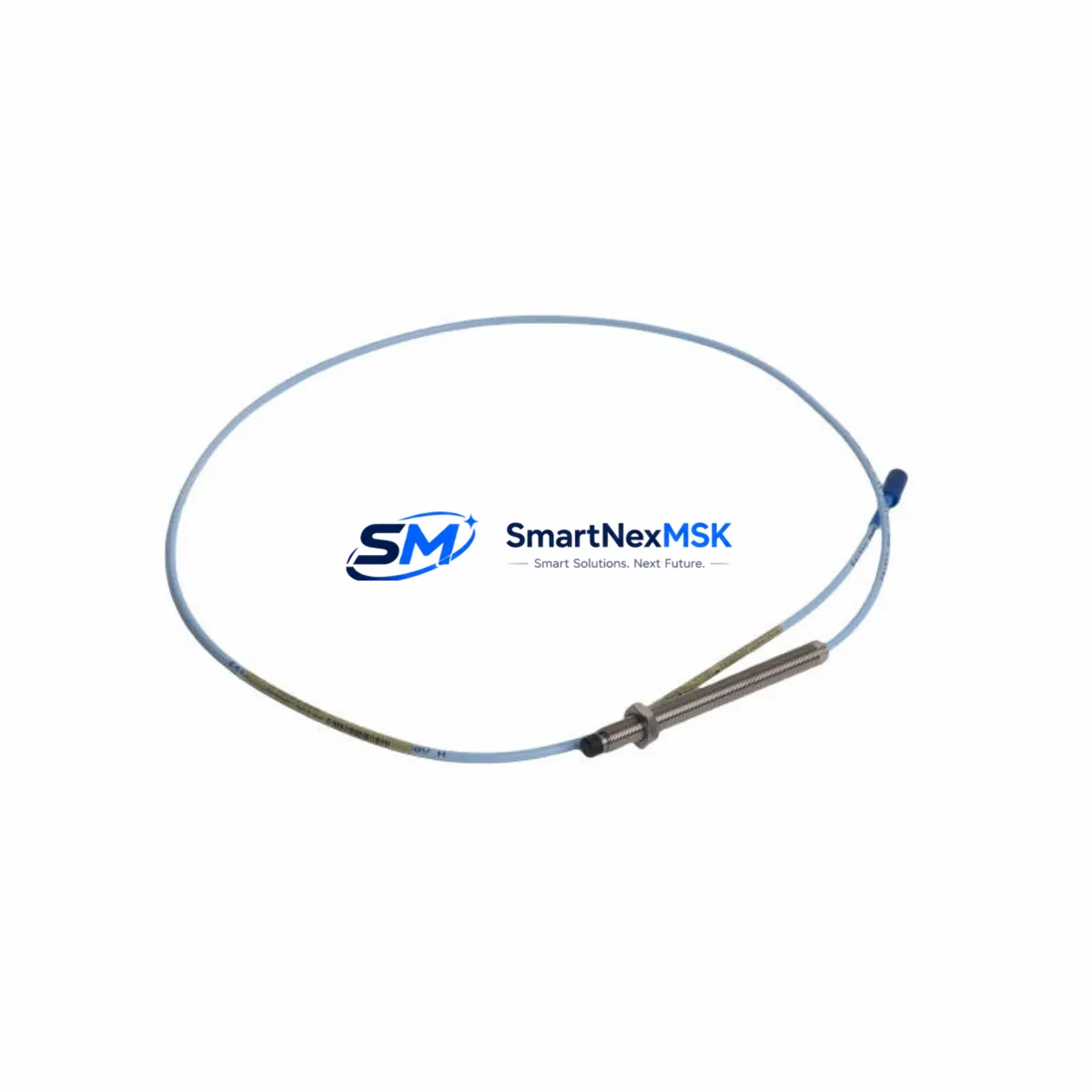
The Bently Nevada 330103-02-10-10-02-CN is an 8mm proximity transducer designed for seamless integration into existing 3300 XL vibration monitoring systems. Whether you are replacing a failed unit on a critical rotating machine, upgrading an aging condition monitoring platform, or restoring a legacy control cabinet to full operational status, this transducer delivers the dimensional accuracy, signal linearity, and electrical compatibility required for a smooth, low-risk retrofit.
Industrial facilities running legacy Bently Nevada 3300 XL monitor racks — including the 3300/16 Dual Voting, 3300/20 Radial Vibration, and 3300/25 Thrust Position monitors — frequently encounter the need to replace worn or damaged proximity transducers without triggering a full system overhaul. The 330103-02-10-10-02-CN is engineered to serve exactly this role: a verified drop-in replacement that preserves existing wiring, connector pinouts, and signal conditioning parameters.
Upgrade Compatibility Table
| Parameter | 330103-02-10-10-02-CN | Notes |
|---|---|---|
| Probe Diameter | 8 mm | Standard 3300 XL probe size |
| Cable Length | 1.0 m (extension cable required) | Pair with 330130-045-00-00 extension cable |
| Connector Type | Coaxial, 3-pin | Compatible with standard 3300 XL driver input |
| Driver Compatibility | 3300 XL 8mm Proximitor Sensor | Use with 330180-X1-05 or equivalent driver |
| Gap Voltage Range | −10 VDC nominal at 1.0 mm gap | Verify gap setting during commissioning |
| Communication Protocol | Analog 4–20 mA / voltage output | No protocol migration required |
| Mounting Thread | M10 × 1.0 | Confirm bracket thread before installation |
| Installation Requirement | Bracket-mounted, field-adjustable gap | Use gap-setting tool during commissioning |
| Replacement Recommendation | Direct drop-in for same SKU | No firmware or rack reconfiguration needed |
| Warranty | 12 Months | Covers manufacturing defects, DOA replacement |
Retrofit Planning for Existing Automation Systems
Successful retrofit of the 330103-02-10-10-02-CN into an operating plant environment requires systematic pre-installation verification. Begin by auditing the existing 3300 XL monitor rack configuration. Confirm that the installed Proximitor driver — typically a 330180-X1-05 or 330180-X1-CN variant — is calibrated for 8mm probe geometry. Mismatched driver-probe combinations are the leading cause of erroneous gap voltage readings and false trip events during post-replacement commissioning.
Next, inspect the existing extension cable assembly. The 330130-045-00-00 extension cable (4.5 m) is the most common pairing in field installations; however, some legacy cabinets use the shorter 330130-020-00-00 (2.0 m) variant. Verify cable continuity and shield integrity before reuse. A degraded shield on the extension cable will introduce electrical noise that mimics mechanical vibration, leading to nuisance alarms on the 3300/20 Radial Vibration monitor channel.
For installations where the 3300 XL rack interfaces with a DCS or safety system — such as a Honeywell Experion PKS, Emerson DeltaV, or ABB System 800xA — confirm that the analog input card scaling on the DCS side matches the transducer’s output range. No changes to the DCS I/O configuration are typically required for a like-for-like transducer replacement, but the engineering team should validate the 4–20 mA loop integrity and confirm that the barrier or isolator module in the marshalling cabinet is functioning within specification.
If the control cabinet also houses a 3500 series rack alongside the 3300 XL system, note that the 3500/42M Proximitor/Seismic Monitor uses a different driver architecture and is not interchangeable with 3300 XL drivers. Maintain clear labeling on all cable runs to prevent cross-connection during maintenance windows. Similarly, if a TK-3 or TK-3e keyphasor module is installed in the rack, verify that the keyphasor signal path is undisturbed during transducer replacement, as loss of keyphasor reference will disable phase-referenced vibration analysis across all channels.
For facilities planning a broader migration from 3300 XL to 3500 series architecture, the 330103-02-10-10-02-CN can serve as an interim solution, maintaining monitoring continuity on legacy channels while new 3500/42M cards and 190501 Proximitor sensors are staged for installation. This phased approach minimizes total downtime and allows engineering teams to validate the new system in parallel before cutover.
Downtime Control During System Migration
Minimizing unplanned downtime during transducer replacement requires a structured hot-swap protocol. Where process conditions permit, coordinate the replacement during a scheduled maintenance window rather than a forced outage. Before removing the failed transducer, document the existing gap voltage reading from the 3300 XL monitor front panel or the connected DCS historian. This baseline value is essential for verifying correct reinstallation of the 330103-02-10-10-02-CN.
During installation, use a calibrated gap-setting tool to achieve the nominal −10 VDC gap voltage at the specified 1.0 mm air gap. After mechanical installation, restore power to the Proximitor driver and allow a 5-minute warm-up period before recording the new gap voltage. Compare against the documented baseline. A deviation of more than ±0.5 VDC from the original reading warrants re-inspection of the probe mounting bracket, thread engagement depth, and target material surface condition.
Once gap voltage is confirmed, verify that the 3300 XL monitor channel has cleared any latched alarms and is displaying a live vibration reading consistent with machine operating state. If the channel remains in alarm, check the monitor’s OK relay status and confirm that the Proximitor driver’s OK LED is illuminated. A non-illuminated OK LED indicates a wiring fault, gap out-of-range condition, or driver power supply issue — all of which must be resolved before returning the machine to service.
Throughout the replacement process, maintain continuous communication with the control room operator to ensure that any transient alarm states are acknowledged and logged. Preserve the original program logic in the DCS or safety PLC without modification. No changes to ladder logic, function block diagrams, or HMI faceplate configurations are required for a transducer-level replacement within the 3300 XL architecture.
Retrofit Support FAQ
Q1: Is the 330103-02-10-10-02-CN a direct replacement for the original Bently Nevada part?
Yes. The 330103-02-10-10-02-CN is a verified direct replacement for the original Bently Nevada part of the same SKU. It maintains identical probe geometry, connector type, cable interface, and output characteristics, ensuring compatibility with existing 3300 XL Proximitor drivers and monitor racks without requiring any rack reconfiguration or recalibration of the monitor card.
Q2: What wiring checks are required before installation?
Inspect the coaxial extension cable for continuity and shield integrity. Verify that the Proximitor driver terminal block connections are secure and free of corrosion. Confirm that the barrier or isolator module in the marshalling cabinet is within specification. Check that the cable run is free of sharp bends or pinch points that could degrade signal quality after installation.
Q3: How is compatibility with the 3300 XL monitor verified after installation?
After installation, confirm that the gap voltage displayed on the 3300 XL monitor front panel falls within the acceptable range for the machine’s normal operating clearance. Verify that the monitor’s OK relay is energized and that the channel is displaying a live, stable vibration reading. Cross-check the reading against the DCS historian trend to confirm signal continuity through the full signal chain from probe to control system.
Q4: What does the 12-month warranty cover?
The 12-month warranty covers manufacturing defects and dead-on-arrival (DOA) units. Each unit undergoes pre-shipment functional testing to verify output linearity, connector integrity, and cable assembly quality. In the event of a warranty claim, contact sales@smartnexmsk.com with the order reference and a description of the fault. Replacement units are dispatched within 3 business days of claim verification.
© 2026 SMARTNEXMSK. All rights reserved.
Original Source: https://smartnexmsk.com
Contact: sales@smartnexmsk.com | +86 18259474341


