Bently Nevada 330103-02-12-05-02-05 3300 XL Proximity Transducer: Retrofit-Ready Replacement for Legacy Vibration Monitoring Systems
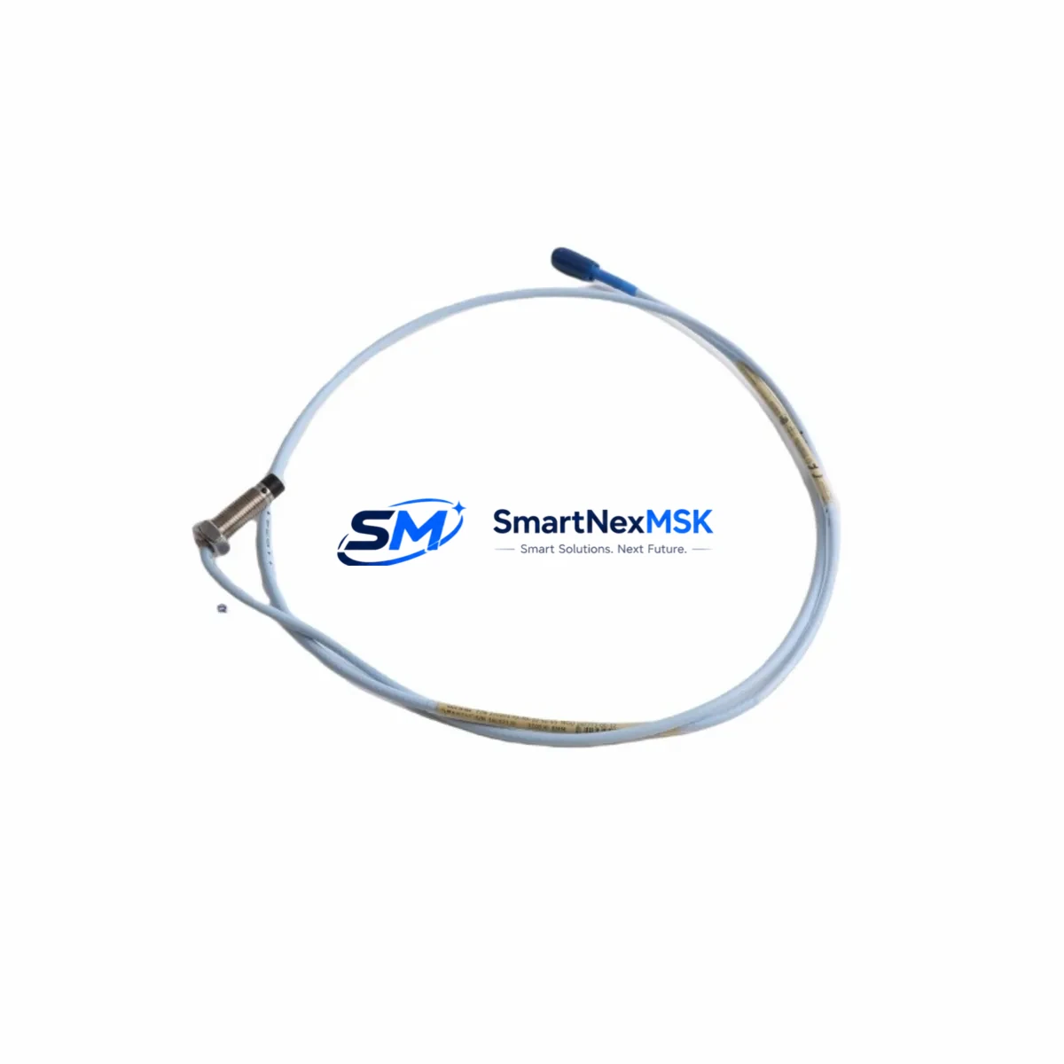
The Bently Nevada 330103-02-12-05-02-05 is an 8mm eddy-current proximity transducer engineered for the 3300 XL Series vibration monitoring platform. As legacy machinery protection systems age and original components reach end-of-life, this transducer serves as a direct retrofit solution for facilities operating rotating equipment — including turbines, compressors, pumps, and motors — where continuous shaft vibration and position monitoring is mission-critical.
Whether you are replacing a failed sensor in an existing 3300 XL rack, upgrading from an older 3300 Series (non-XL) installation, or restoring a dormant monitoring loop, the 330103-02-12-05-02-05 delivers the dimensional accuracy, gap voltage linearity, and cable configuration required for seamless field integration without reprogramming the monitor or recalibrating the entire channel.
Upgrade Compatibility Table
| Parameter | 330103-02-12-05-02-05 (This Unit) | Legacy / Predecessor Models |
|---|---|---|
| Probe Tip Diameter | 8mm | 5mm / 11mm (different SKU suffix) |
| Cable Length | 0.5m integral + extension cable | Varies by suffix; verify before ordering |
| Extension Cable Compatibility | 330130 / 330180 Series extension cables | Must match total system cable length for calibration |
| Driver / Proximitor Compatibility | 3300 XL 8mm Proximitor (e.g. 330180-X1-05) | Not compatible with 3300 5mm or 11mm Proximitors |
| Monitor Rack Compatibility | 3300/16 Rack, 3500 Series (with correct I/O module) | Verify I/O module part number before installation |
| Communication Protocol | Analog 4–20mA / voltage output via Proximitor | Same — no protocol migration required |
| Installation Requirement | Threaded mounting, gap set to 1.0–1.5mm nominal | Same thread spec; re-gap required after replacement |
| Retrofit Recommendation | Direct drop-in for 8mm 3300 XL transducer positions | Confirm suffix digits 3–6 match your system config |
| Commissioning Focus | Gap voltage verification, OK relay check, alarm setpoint confirmation | Re-verify after any transducer swap |
| Warranty | 12-Month Warranty — covers manufacturing defects and functional failure under normal operating conditions | |
Retrofit Planning for Existing Automation Systems
Integrating the 330103-02-12-05-02-05 into an existing machinery protection architecture requires a structured review of the full signal chain. The transducer does not operate in isolation — it functions as part of a three-component system alongside the 330180 Series 3300 XL 8mm Proximitor (the signal conditioning driver) and the appropriate extension cable, typically from the 330130 Series. The total cable length — integral cable plus extension — must match the calibrated system length specified on the Proximitor label. Substituting a transducer with a different integral cable length without recalibrating the Proximitor will introduce measurement error and may trigger false OK-relay dropout.
For facilities running a 3300/16 Rack, the monitor cards — such as the 3300/25 Dual Voting or 3300/46 Thrust Position Monitor — receive the conditioned signal from the Proximitor and compare it against programmed alarm and danger setpoints. Before swapping the transducer, engineers should document the existing gap voltage (typically –10.0 VDC at nominal gap), the OK-relay threshold, and the alarm setpoints stored in the monitor. These values do not change with a like-for-like transducer replacement, but they must be verified post-installation to confirm the new transducer’s output matches the calibration curve.
Sites that have migrated or are planning to migrate from the 3300 Series to the 3500 Series machinery protection platform should note that the 3500 system uses dedicated I/O modules — such as the 3500/42M Proximitor/Seismic Monitor — which accept the same 8mm transducer and Proximitor combination. This means the 330103-02-12-05-02-05 remains compatible across both generations, protecting your sensor investment during a phased platform upgrade.
In control cabinet environments where the Proximitor is mounted in a 3300 XL Proximitor enclosure or a field junction box, verify that terminal wiring follows the color-coded scheme: the transducer’s coaxial cable connects to the Proximitor input, and the Proximitor’s output terminals feed the monitor rack via shielded twisted-pair. Grounding discipline is critical — the shield must be grounded at one end only to prevent ground loops that corrupt the vibration signal.
For plants running DCS integration via a System 1 asset management platform or a third-party historian, the analog output from the Proximitor feeds into the DCS I/O card as before. No changes to the DCS tag configuration, scaling, or HMI faceplate are required when performing a like-for-like transducer replacement. However, if the replacement is part of a broader upgrade that includes changing the Proximitor model or monitor card, the DCS engineer should verify the output scaling (mV/mil or mV/µm) remains consistent with the historian’s engineering unit configuration.
Downtime Control During System Migration
Replacing a proximity transducer on live rotating equipment requires careful coordination between the maintenance team, the control room operator, and — where applicable — the safety system engineer. The recommended approach is to schedule the swap during a planned maintenance window when the machine can be safely brought to rest. However, in facilities where continuous operation is required, a temporary bypass of the OK relay and alarm channel — with written authorization and a defined time limit — allows the transducer to be replaced without triggering an automatic shutdown.
Before removing the old transducer, record the current gap voltage reading from the monitor front panel or the System 1 display. After installing the 330103-02-12-05-02-05 and threading it to the correct gap (verified with a feeler gauge or by monitoring the gap voltage in real time), confirm the OK relay energizes and the gap voltage falls within the –10.0 ±0.5 VDC nominal range. Only then should the bypass be removed and the channel returned to normal protection mode.
The original program logic in the monitor — including the alarm setpoints, danger setpoints, time delays, and voting configuration — is stored in the monitor card’s non-volatile memory and is not affected by the transducer replacement. This means there is no need to re-download a program or reconfigure the monitor after a like-for-like swap, significantly reducing the risk of introducing configuration errors during the maintenance event. The total expected downtime for a single-channel transducer replacement by an experienced technician is typically under two hours, including gap setting, verification, and documentation.
Retrofit Support FAQ
Q1: Is the 330103-02-12-05-02-05 a direct replacement for my existing 3300 XL 8mm transducer?
A: Yes, provided the suffix digits of your existing transducer match. The suffix encodes the integral cable length, connector type, and temperature rating. Confirm digits 3 through 6 of your existing part number match 02-12-05-02 before ordering. If your existing transducer has a different suffix, contact us with your full part number for a compatibility assessment.
Q2: Do I need to recalibrate the Proximitor after replacing the transducer?
A: A like-for-like replacement (same probe diameter, same integral cable length, same Proximitor model) does not require Proximitor recalibration. You must, however, re-set the physical gap and verify the gap voltage output falls within the specified range. If the total system cable length changes for any reason, the Proximitor must be recalibrated to the new length.
Q3: What wiring checks should I perform before powering up the new transducer?
A: Verify the coaxial connection between the transducer and the extension cable is fully seated and the connector is finger-tight. Check that the extension cable’s output connector is correctly seated in the Proximitor input. Confirm the Proximitor power supply (typically –24 VDC) is within specification. Inspect the shield grounding point and ensure continuity from the transducer tip to the Proximitor input terminal. Megger testing is not recommended on proximity transducer cables.
Q4: What does the 12-month warranty cover, and how is it processed?
A: The 12-month warranty covers manufacturing defects and functional failure under normal operating conditions, including signal output out of specification, OK relay malfunction, and physical defects in the probe body or cable. It does not cover damage caused by incorrect installation, overvoltage, mechanical impact, or chemical exposure. To initiate a warranty claim, contact sales@smartnexmsk.com with your order number, installation date, and a description of the fault. Replacement units are shipped after fault verification.
© 2026 SMARTNEXMSK. All rights reserved.
Original Source: https://smartnexmsk.com
Contact: sales@smartnexmsk.com | +86 18259474341


