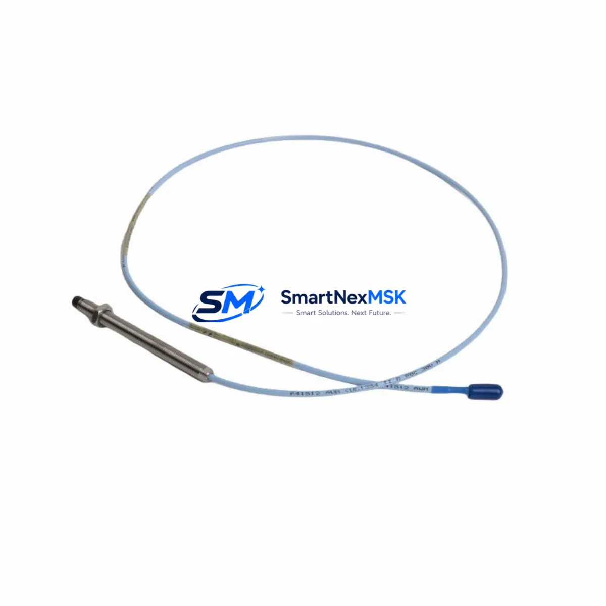
Bently Nevada 330103-03-07-05-02-00 Spare 3300 XL Automation
The Bently Nevada 330103-03-07-05-02-00 is an original eddy-current proximity transducer engineered for the 3300 XL Series continuous machinery monitoring system. Designed for critical rotating equipment applications — including turbines, compressors, pumps, and gearboxes — this transducer delivers precise radial vibration, axial position, and differential expansion measurements essential to plant uptime and predictive maintenance programs. Sourced as a genuine original spare, each unit undergoes pre-shipment functional verification to ensure it meets Bently Nevada factory specifications before dispatch.
For maintenance engineers managing aging DCS or PLC-integrated monitoring architectures, the 330103-03-07-05-02-00 represents a direct, drop-in replacement that eliminates the need for recalibration of the monitoring rack. Its 5-meter extension cable configuration and standard 8 mm tip diameter make it interchangeable within existing 3300 XL probe-driver-extension cable assemblies without modification to conduit routing or junction box layouts. Procurement engineers can rely on a 12-month warranty and documented traceability to support MRO inventory justification and asset management records.
Spare Maintenance Table
| Parameter | Specification |
|---|---|
| Part Number | 330103-03-07-05-02-00 |
| Brand | Bently Nevada |
| Series | 3300 XL |
| Type | Eddy-Current Proximity Transducer |
| Tip Diameter | 8 mm |
| Cable Length | 5 m (integral) |
| Sensitivity | 7.87 V/mm (200 mV/mil) |
| Linear Range | 0.25 – 2.25 mm (10 – 90 mil) |
| Operating Temperature | -35°C to +177°C |
| Supply Voltage | -24 VDC (nominal) |
| Output | DC voltage proportional to gap |
| Compatibility | 3300 XL 8 mm Extension Cable & Driver assemblies |
| Installation | Direct replacement; no recalibration required |
| Application Environment | Turbines, compressors, pumps, gearboxes |
| Origin | USA |
| Warranty | 12 Months |
| Condition | Original, pre-shipment tested |
Maintenance Planning for Continuous Operation
When replacing the 330103-03-07-05-02-00 during a planned outage or emergency shutdown, a thorough inspection of the surrounding measurement chain is essential to prevent repeat failures and ensure signal integrity across the monitoring loop. Maintenance teams should begin by verifying the paired 3300 XL 8 mm Extension Cable (typically a 330130-series assembly) for jacket abrasion, connector corrosion, or continuity loss — a degraded cable is the most common cause of premature transducer failure in high-vibration environments.
The associated 3300 XL Proximitor Sensor (driver module, such as the 330180 or 330190 series) should be bench-tested for output voltage linearity before reinstallation. If the Proximitor shows drift beyond ±0.5 V from nominal at the standard gap, it should be replaced concurrently to avoid masking a latent fault. Inspect the terminal block and field wiring within the junction box for loose terminations, moisture ingress, or insulation breakdown — particularly on installations older than five years.
At the monitoring rack level, confirm that the 3500/40M Proximitor Monitor or equivalent 3300 rack card is reading within its configured alert and danger setpoints. A transducer swap is an ideal opportunity to audit barrier isolators or Zener barriers used in hazardous-area installations, as these components age independently and can introduce signal attenuation that mimics transducer degradation. Similarly, check the DC power supply module feeding the Proximitor circuit — supply voltage outside the -24 VDC ±1 V tolerance will shift the transducer’s linear range and produce false readings.
For systems integrated into a DCS historian or PLC analog input card, verify the 4–20 mA or voltage signal at the I/O termination panel after replacement to confirm end-to-end loop integrity. If the plant uses a System 1 Evolution or equivalent condition monitoring software, update the transducer asset record and re-baseline the vibration trend data to avoid false alarms triggered by the new probe’s slightly different gap voltage. Facilities running legacy 3300 Series (non-XL) racks should confirm driver compatibility before installation, as the XL series uses a revised sensitivity standard.
Site Replacement Workflow
Step 1 — Isolation & Lockout: Follow site LOTO procedures. De-energize the Proximitor supply at the rack or field junction box. Allow the machine to reach a safe, stationary state before accessing the probe mounting location.
Step 2 — Gap Measurement & Documentation: Record the existing probe gap (typically 1.0–1.5 mm for radial vibration applications) using a feeler gauge or the Proximitor output voltage before removal. This baseline simplifies reinstallation and gap-setting of the replacement unit.
Step 3 — Removal: Unscrew the 330103-03-07-05-02-00 from the probe holder. Inspect the mounting threads and bracket for wear or corrosion. Clean the target area on the shaft to remove any oxide buildup that could affect the new probe’s linear range.
Step 4 — Installation: Thread the replacement transducer into the holder. Set the gap to the documented baseline or per the OEM specification (typically 1.27 mm / 50 mil for 8 mm probes). Secure the locknut and route the integral cable to the junction box, avoiding sharp bends or contact with hot surfaces.
Step 5 — Verification: Re-energize the Proximitor supply and confirm the output voltage at the junction box matches the expected value for the set gap (approximately -10.2 VDC at 1.27 mm gap). Check the monitoring system display for a valid, stable reading before returning the machine to service.
Step 6 — Documentation: Update the CMMS work order with the replaced part number, installation date, gap setting, and post-installation readings. Retain the warranty documentation for the 12-month coverage period.
Spare Parts Support FAQ
Q1: Is the 330103-03-07-05-02-00 a direct replacement for older 330103-series probes?
A: The 330103-03-07-05-02-00 is part of the 3300 XL 8 mm probe family and is directly interchangeable with other 330103-series variants sharing the same tip diameter and cable length, provided the paired extension cable and Proximitor driver are also XL-series components. Mixing XL probes with non-XL drivers will result in sensitivity mismatch and inaccurate readings.
Q2: What pre-shipment testing is performed on this spare?
A: Each unit is functionally verified for output voltage linearity across the specified gap range, connector integrity, and cable continuity before dispatch. A test report is available upon request for quality-critical installations.
Q3: How should this spare be stored in an MRO inventory?
A: Store in the original packaging in a dry, temperature-controlled environment (0°C to 40°C) away from strong magnetic fields. Inspect the connector and cable jacket annually. Shelf life under proper storage conditions exceeds five years without performance degradation.
Q4: What is covered under the 12-month warranty?
A: The warranty covers manufacturing defects, output signal failure under normal operating conditions, and connector integrity. It does not cover damage resulting from incorrect gap setting, mechanical impact, chemical exposure, or use outside the specified operating temperature range. Warranty claims are supported with replacement or full refund within the coverage period.
© 2026 SMARTNEXMSK. All rights reserved.
Original Source: https://smartnexmsk.com
Contact: sales@smartnexmsk.com | +86 18259474341


