Bently Nevada 330103-03-08-10-01-00 Retrofit-Ready Proximity Probe for 3300 XL Control Systems
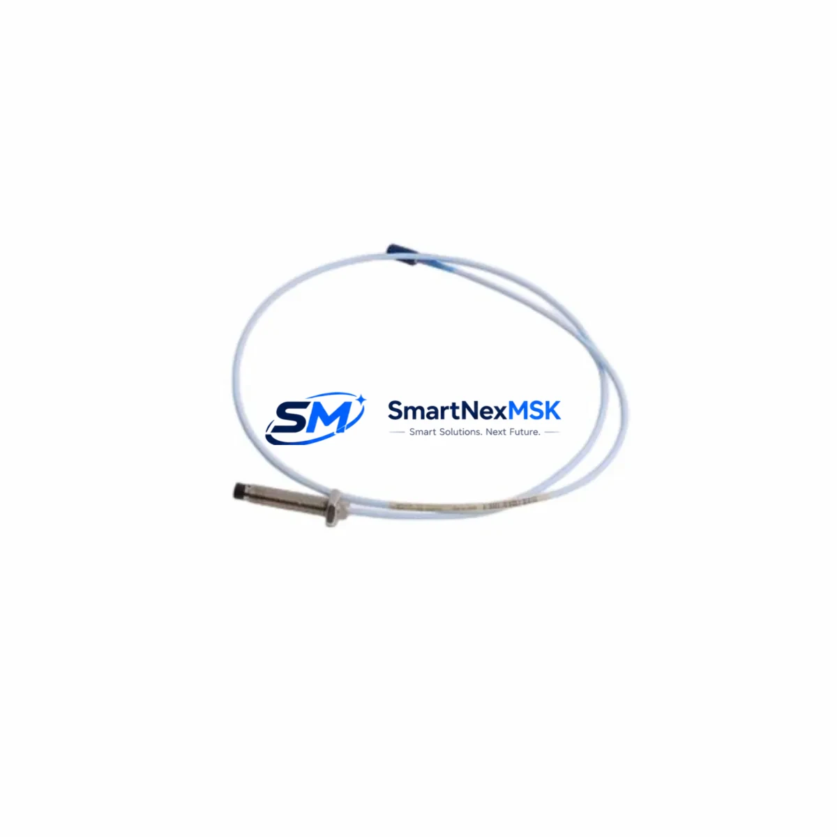
The Bently Nevada 330103-03-08-10-01-00 is an 8mm eddy-current proximity probe engineered for the 3300 XL Series continuous machinery monitoring platform. As legacy 3300 Series installations approach end-of-support milestones, plant engineers and reliability teams are actively sourcing verified replacement probes that maintain signal chain integrity without requiring full system overhauls. This unit delivers a direct, retrofit-ready solution: same connector pinout, same sensitivity factor (200 mV/mil, 7.87 V/mm), and full compatibility with the 3300 XL proximitor/seismic transducer driver — enabling a smooth transition from worn or discontinued probe assemblies with minimal downtime exposure.
Whether you are replacing a failed probe on a critical compressor train, upgrading a turbine monitoring loop, or restoring a mothballed control cabinet, the 330103-03-08-10-01-00 integrates directly with existing Bently Nevada 3300 XL Proximitor modules such as the 3300/16 and 3300/20 series drivers. The probe’s armored extension cable and integral connector are pre-terminated to standard Bently Nevada specifications, eliminating field re-termination risk during hot-swap maintenance windows.
Upgrade Compatibility Table
| Parameter | 330103-03-08-10-01-00 | Notes / Retrofit Guidance |
|---|---|---|
| Probe Diameter | 8 mm | Matches standard 3300 XL probe bore; no bracket modification required |
| Cable Length | 3 m (extension cable) | Verify total system cable length does not exceed proximitor driver spec (typically 5 m or 9 m system) |
| Sensitivity | 200 mV/mil (7.87 V/mm) | Matches 3300 XL Proximitor calibration; no re-scaling in DCS/historian required |
| Gap Voltage Range | −10 VDC to −18 VDC | Confirm power supply rail on 3300 XL Proximitor module before installation |
| Connector Interface | Standard Bently Nevada integral connector | Direct plug-in to existing 3300 XL Proximitor input; no adapter required |
| Communication Compatibility | Analog (4–20 mA / voltage output via Proximitor) | Compatible with MODBUS RTU, PROFIBUS DP, and 4–20 mA DCS input cards downstream |
| Replacement Scope | Drop-in for 330103 series probes | Verify suffix codes: cable length (03=3m), probe length (08=8mm), temperature range (10=standard) |
| Commissioning Requirement | Gap voltage verification + OK relay check | Use Bently Nevada 3300 XL commissioning procedure; record gap voltage at 40 mil nominal |
| Warranty | 12 Months | Covers manufacturing defects; includes pre-shipment functional test certificate |
Retrofit Planning for Existing Automation Systems
Successful integration of the 330103-03-08-10-01-00 into an existing machinery protection loop begins well before the probe reaches the field. During the planning phase, engineers should pull the existing loop drawing and confirm the Proximitor model installed in the control cabinet — typically a 3300/16-02-01-00 or 3300/20-01-00 driver card seated in a 3300 rack assembly. The rack’s backplane power distribution must be verified to supply a stable −24 VDC bias to the Proximitor, as voltage sag under load can shift the probe’s operating gap and trigger nuisance OK relay trips.
Terminal block wiring at the junction box should be documented before disconnecting the old probe. The 330103 series uses a two-conductor shielded cable (signal and shield/return), and the shield must be grounded at one end only — typically at the Proximitor input terminal — to avoid ground loops that corrupt vibration readings. If the existing installation used a 3300/05 barrier or a Zener barrier for intrinsically safe areas, confirm that the new probe’s capacitance and inductance parameters remain within the barrier’s entity parameters before energizing.
For plants running a System 1 Evolution or System 1 Classic condition monitoring platform, the probe replacement does not require any database reconfiguration provided the Proximitor model and sensitivity factor remain unchanged. However, if the site is migrating from an older 3300 Series (non-XL) rack to a 3300 XL rack as part of a broader control cabinet upgrade, the System 1 point configuration will need to be updated to reflect the new Proximitor firmware version and any changes to the OK relay logic thresholds.
I/O expansion projects that add new measurement points — such as installing a second radial vibration channel on a previously single-channel bearing — will require an additional 3300 XL Proximitor slot in the rack. In these cases, the 3300 rack’s power supply module (e.g., 3300/15 power supply) should be load-checked to confirm it can support the additional Proximitor current draw. Pairing the new probe with a 3300/25 keyphasor module is recommended when phase-referenced vibration analysis is required for balancing or orbit plot generation.
HMI screens tied to the existing vibration monitoring loop — whether running on a Rockwell FactoryTalk View, Siemens WinCC, or a standalone Bently Nevada operator display — typically do not require modification when performing a like-for-like probe swap. However, if the retrofit involves changing the measurement range or adding a new channel, the HMI tag database and alarm setpoint configuration should be reviewed and updated before returning the machine to service. Communication links between the 3300 XL rack and the plant DCS (via a 3300/55 communication gateway or a MODBUS TCP/IP interface module) should be verified live during commissioning to confirm that vibration, gap, and OK status signals are being received correctly at the control room.
Downtime Control During System Migration
Minimizing unplanned downtime during a proximity probe replacement requires a structured pre-outage preparation protocol. Before the maintenance window opens, the replacement 330103-03-08-10-01-00 should be bench-tested using a Bently Nevada TK-3 proximity calibrator or equivalent to confirm sensitivity, gap voltage linearity, and OK relay operation. Having a verified spare on the shelf — rather than ordering reactively after a failure — is the single most effective downtime reduction measure for rotating machinery protection systems.
During the outage, the original program logic in the machinery protection system should not be modified unless the replacement scope explicitly requires it. The Proximitor’s OK relay setpoints (typically −2 VDC to −18 VDC for the OK window) should be recorded before disconnection and verified after the new probe is installed and gapped. If the plant uses a Bently Nevada 3500 Series rack in parallel for trip logic, ensure that the 3500/42M or 3500/45 position monitor cards are bypassed or placed in maintenance mode before probe removal to prevent spurious trips during the swap.
After installation, the gap voltage should be set to the nominal value specified on the machine’s vibration monitoring data sheet — commonly −10 VDC for a 40 mil (1.0 mm) air gap on a steel shaft. The OK relay should be confirmed closed, and the vibration reading at slow-roll speed should be compared against the historical baseline stored in the condition monitoring system. Any deviation greater than 10% from the baseline slow-roll vector warrants investigation before returning the machine to full-speed operation. Documenting the as-left gap voltage, slow-roll amplitude, and phase angle in the plant’s maintenance management system (CMMS) creates a traceable record that supports future reliability analysis and warranty claims.
Retrofit Support FAQ
Q1: Is the 330103-03-08-10-01-00 a direct replacement for other 330103 suffix variants?
The 330103 base part number covers a family of 8mm proximity probes differentiated by cable length, probe body length, and temperature rating encoded in the suffix. The -03-08-10-01-00 variant specifies a 3m extension cable, 8mm probe diameter, standard temperature range, and integral connector. It is a direct replacement for units with the same suffix. For variants with different cable lengths (e.g., 330103-03-05-10-01-00 for 5m systems), the total system cable length must be recalculated against the Proximitor driver specification before substitution.
Q2: What commissioning steps are required after installation?
After mechanical installation and cable connection, set the probe-to-shaft gap to the value specified on the machine data sheet (typically 40 mil / 1.0 mm for a −10 VDC gap voltage). Confirm the Proximitor OK relay is closed and that the gap voltage is within the OK window (−2 VDC to −18 VDC). Record the slow-roll vibration amplitude and phase angle as a new baseline. Verify that the DCS and condition monitoring system are receiving valid signals before releasing the machine for startup.
Q3: Can this probe be used in hazardous (Ex) classified areas?
The standard 330103-03-08-10-01-00 is not intrinsically safe rated. For Zone 1 or Zone 2 hazardous area installations, a certified Zener barrier or galvanic isolator must be installed between the probe/Proximitor loop and the control system. Confirm the barrier’s entity parameters are compatible with the probe’s cable capacitance and inductance before installation. Consult the applicable ATEX or IECEx documentation for your specific installation requirements.
Q4: What does the 12-month warranty cover, and is a test certificate included?
Every 330103-03-08-10-01-00 unit shipped by SMARTNEXMSK is functionally tested prior to dispatch. The 12-month warranty covers manufacturing defects in materials and workmanship under normal operating conditions. A pre-shipment test certificate confirming sensitivity, gap voltage linearity, and OK relay operation is included with each unit. Warranty claims are processed via our sales team; units must be returned in original packaging with the test certificate reference number.
© 2026 SMARTNEXMSK. All rights reserved.
Original Source: https://smartnexmsk.com
Contact: sales@smartnexmsk.com | +86 18259474341


