Bently Nevada 330103-03-12-50-02-00 3300 XL Spare: Precision Proximity Transducer for Industrial Downtime Recovery
The Bently Nevada 330103-03-12-50-02-00 is an original proximity transducer engineered for the 3300 XL Series vibration monitoring system — one of the most widely deployed machinery protection platforms in rotating equipment applications worldwide. Whether you are managing a planned turnaround, responding to an unplanned trip, or building a critical spare inventory for your control room, this transducer delivers the measurement accuracy and system compatibility required to restore continuous operation with confidence.
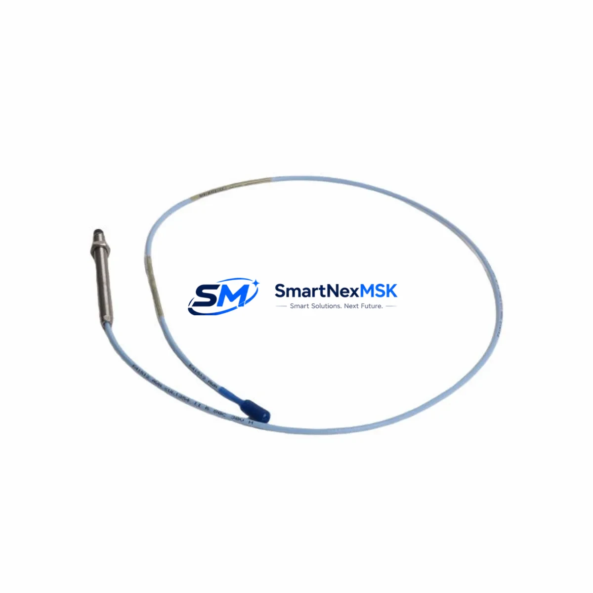
Designed for non-contact displacement and vibration measurement, the 330103-03-12-50-02-00 operates as part of a three-component proximity system alongside the extension cable and proximitor/oscillator driver. Its 5 mm tip diameter, 5 mm linear range, and 200 mV/mil sensitivity make it a precision instrument for shaft radial vibration, axial position, and differential expansion monitoring on turbines, compressors, pumps, and gearboxes. Each unit shipped by SMARTNEXMSK is tested prior to dispatch and backed by a 12-month warranty, ensuring your maintenance team receives a verified, ready-to-install spare.
Spare Maintenance Table
| Parameter | Specification |
|---|---|
| Part Number | 330103-03-12-50-02-00 |
| Brand | Bently Nevada |
| Series | 3300 XL Proximity Transducer System |
| Tip Diameter | 5 mm |
| Linear Range | 5 mm (0.2 in) |
| Sensitivity | 200 mV/mil (7.87 V/mm) |
| Cable Length | 3 m (integral) |
| Extension Cable Compatibility | 3300 XL 330130 Series Extension Cables |
| Driver / Proximitor Compatibility | 3300 XL 330180 / 330185 Proximitor Modules |
| Target Material | AISI 4140 Steel (standard) |
| Operating Temperature | -35°C to +120°C |
| Ingress Protection | IP67 |
| Connector Type | MIL-C-5015 (standard) |
| Application | Radial vibration, axial position, differential expansion |
| Typical Installations | Steam turbines, gas compressors, centrifugal pumps, gearboxes |
| Mounting Thread | M10 × 1 (standard) |
| Origin | USA |
| Condition | Original, tested before shipment |
| Warranty | 12 Months |
Maintenance Planning for Continuous Operation
When a proximity transducer such as the 330103-03-12-50-02-00 is flagged during a routine control cabinet inspection or triggers a high-vibration alarm on the 3300 XL rack, experienced maintenance engineers know that the transducer itself is rarely the only component that warrants attention. A thorough fault isolation and replacement workflow should encompass the entire signal chain.
Begin by verifying the 330130 Series extension cable — the coaxial cable connecting the transducer to the proximitor driver. Cable damage, connector corrosion, or impedance mismatch is a frequent root cause of erratic gap voltage readings that can be misdiagnosed as transducer failure. Next, inspect the 330180 or 330185 Proximitor/Oscillator module seated in the 3300 XL rack; a degraded driver will produce incorrect output voltage even with a new transducer installed.
At the rack level, confirm that the 3300 XL power supply module is delivering stable ±24 VDC to the proximitor channel. Voltage sag or ripple on the power rail will directly affect gap voltage calibration and measurement linearity. If the rack houses a 3300/16 or 3300/20 monitor card, verify that the channel configuration — gap voltage setpoints, alert and danger thresholds — matches the replacement transducer’s sensitivity specification before returning the machine to service.
For installations where the 330103-03-12-50-02-00 feeds into a System 1 Evolution or legacy System 1 condition monitoring platform, confirm that the I/O mapping and channel scaling are updated in the software configuration after transducer replacement. Maintenance teams managing older DCS integrations should also check the 4–20 mA output isolator or signal conditioner that converts the proximitor’s voltage output to a process signal for the DCS historian — these isolators age and can introduce offset errors that mask true machinery condition.
During planned outages on rotating equipment, it is best practice to simultaneously inspect terminal blocks and field junction boxes in the proximity system wiring run. Loose terminations and moisture ingress at field junction boxes are a leading cause of intermittent channel faults. Where the machine is equipped with a Keyphasor transducer (typically a 330980 or 330905 series), verify its gap voltage and signal quality as well — the Keyphasor reference is critical for phase-referenced vibration analysis and should be treated as part of the same maintenance event.
For facilities managing aging turbomachinery with legacy 3300 Series (non-XL) racks, the 330103-03-12-50-02-00 is a direct functional replacement in most configurations, but always confirm rack compatibility and proximitor driver pairing before installation. Maintaining a minimum of two spare transducers per critical machine train — alongside matched extension cables and a spare proximitor module — is the recommended inventory posture for facilities with 24/7 uptime requirements.
Site Replacement Workflow
Step 1 — Isolation and Documentation: Before removing the installed transducer, record the existing gap voltage (typically –10 VDC ±0.5 V for a 50-mil gap on standard steel targets) and photograph the connector orientation and cable routing. This baseline is essential for post-installation verification.
Step 2 — Mechanical Removal: De-energize the proximitor channel at the rack. Disconnect the extension cable at the transducer connector. Using the appropriate spanner, unthread the transducer from the mounting bracket. Note the number of turns to reach the original gap setting — this provides a starting reference for the replacement unit.
Step 3 — Replacement Installation: Thread the 330103-03-12-50-02-00 into the bracket to the same approximate depth. Re-energize the channel and measure gap voltage. Adjust transducer depth in small increments until gap voltage falls within the specified linear range. Torque the locknut to the manufacturer’s specification.
Step 4 — Signal Verification: Confirm gap voltage stability over a 5-minute observation period. Check that the monitor card displays a valid vibration reading consistent with machine operating state. If the machine is at rest, a static gap voltage within the linear range confirms correct installation.
Step 5 — System Return: Re-enable monitor channel bypasses if they were activated during maintenance. Update the maintenance management system (CMMS) with the replacement record, including the new transducer serial number and installation date. Log the event in the spare parts consumption record to trigger reorder of a replacement spare.
This workflow minimizes downtime, preserves system compatibility, and ensures the 3300 XL monitoring system is returned to full protective function without introducing new faults through rushed or undocumented replacement procedures.
Spare Parts Support FAQ
Q1: Is the 330103-03-12-50-02-00 compatible with both 3300 XL and legacy 3300 Series racks?
The 330103-03-12-50-02-00 is designed for the 3300 XL proximity system. In most legacy 3300 Series installations it is functionally compatible, provided the extension cable and proximitor driver are also from the 3300 XL family. Always verify the complete system pairing — transducer, extension cable, and proximitor — before installation to ensure calibrated performance.
Q2: What pre-shipment testing is performed on each unit?
Every 330103-03-12-50-02-00 shipped by SMARTNEXMSK undergoes electrical continuity verification, gap voltage output testing against a reference steel target, and connector integrity inspection. Units that do not meet Bently Nevada’s published output specifications are not dispatched. A 12-month warranty covers defects in materials and workmanship from the date of shipment.
Q3: How should this transducer be stored as a long-term spare?
Store in the original packaging or an ESD-safe bag in a dry environment between –20°C and +70°C, away from strong magnetic fields and solvents. Inspect the connector and cable jacket annually. For critical machine trains, a recommended spare holding period is up to 5 years when stored correctly, after which a functional test is advisable before installation.
Q4: Can SMARTNEXMSK support ongoing supply for multi-unit or multi-site procurement?
Yes. SMARTNEXMSK maintains stock of the 330103-03-12-50-02-00 and related 3300 XL system components to support both emergency single-unit orders and planned multi-unit procurement for maintenance contracts. Contact our team to discuss volume pricing, lead times, and consignment stock arrangements for facilities with high-availability requirements.
© 2026 SMARTNEXMSK. All rights reserved.
Original Source: https://smartnexmsk.com
Contact: sales@smartnexmsk.com | +86 18259474341


