Bently Nevada 330103-03-13-10-02-CN Maintenance-Ready Spare for 3300 XL Automation
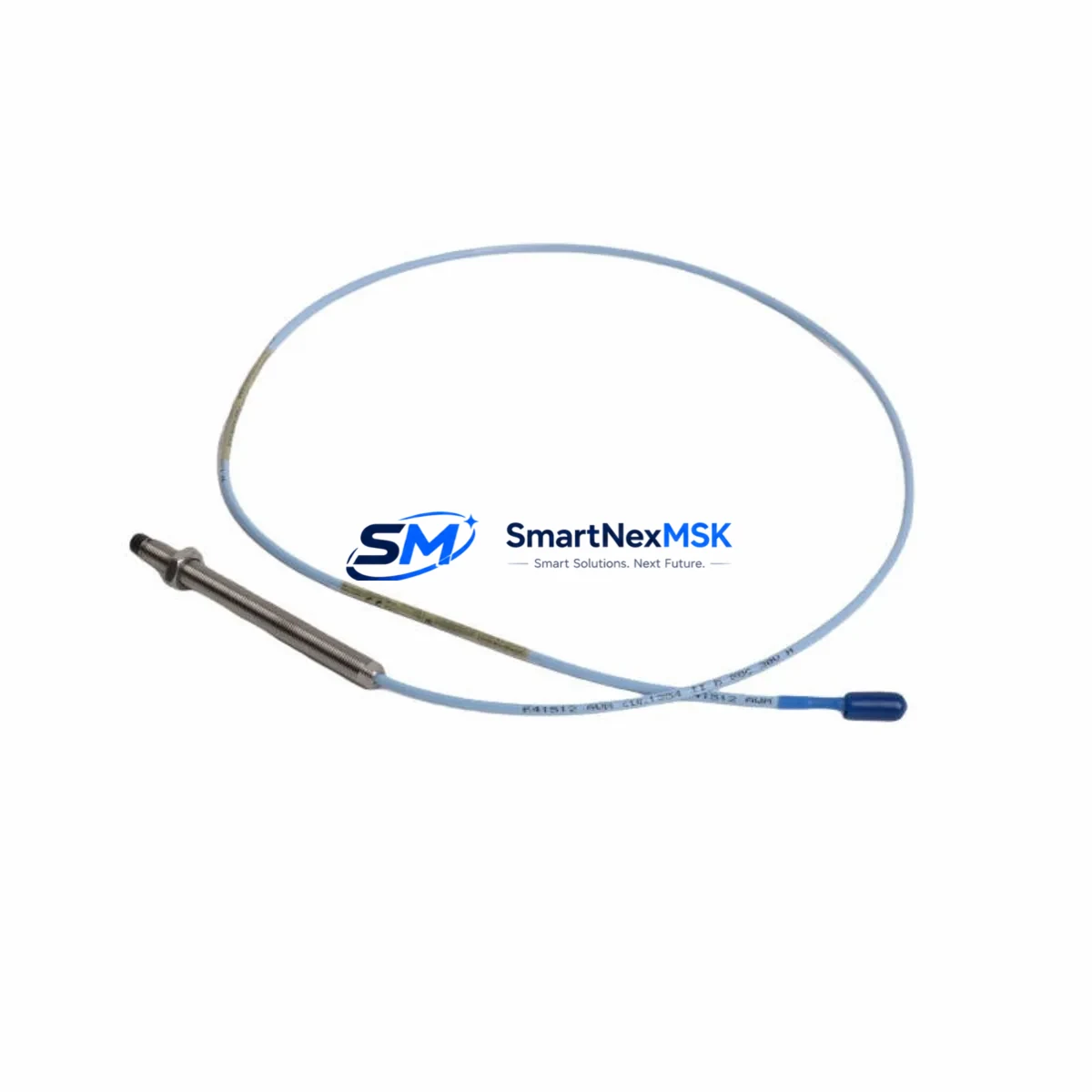
The Bently Nevada 330103-03-13-10-02-CN is an original eddy-current proximity transducer engineered for the 3300 XL continuous monitoring system. Designed for high-reliability rotating machinery protection, this transducer delivers precise non-contact displacement measurement in turbines, compressors, pumps, and other critical rotating assets. For maintenance engineers managing aging DCS or vibration monitoring infrastructure, having a verified spare of the 330103-03-13-10-02-CN on the shelf is a fundamental risk-reduction strategy — one that directly shortens mean time to repair (MTTR) and prevents extended unplanned downtime.
This unit ships fully tested, with original Bently Nevada specifications confirmed prior to dispatch. Each spare is covered by a 12-month warranty and is available for fast worldwide delivery, supporting both emergency replacement and planned maintenance cycles. Whether you are executing a scheduled outage, responding to a vibration alarm, or building out your critical spare inventory, the 330103-03-13-10-02-CN is a direct, compatible replacement for the 3300 XL transducer position in your monitoring loop.
Spare Maintenance Table
| Parameter | Specification |
|---|---|
| Part Number / SKU | 330103-03-13-10-02-CN |
| Brand | Bently Nevada |
| Series | 3300 XL |
| Product Type | Eddy-Current Proximity Transducer |
| Measurement Principle | Non-contact eddy-current displacement |
| Tip Diameter | 8 mm (standard) |
| Cable Length | 1.0 m integral cable (extension cable required for full loop) |
| Sensitivity | 7.87 V/mm (200 mV/mil) nominal |
| Frequency Range | DC to 10,000 Hz |
| Operating Temperature | -35°C to +177°C |
| Target Material Compatibility | AISI 4140 steel (standard); other alloys require calibration verification |
| Connector Type | CN (coaxial, standard Bently Nevada) |
| System Compatibility | 3300 XL Monitoring System; 3500 series with appropriate driver |
| Installation | Threaded probe body, locknut included; gap setting per OEM procedure |
| Application Environment | Turbines, compressors, pumps, gearboxes, motors — rotating machinery |
| Origin | USA (Original Bently Nevada manufacture) |
| Warranty | 12 Months |
| Pre-shipment Testing | Yes — functional and sensitivity verified |
Maintenance Planning for Continuous Operation
When a 330103-03-13-10-02-CN transducer is flagged for replacement — whether due to a sensitivity drift alarm, physical damage, or a scheduled calibration interval — the replacement event is an opportunity to audit the entire vibration monitoring loop and adjacent control cabinet components. Experienced maintenance engineers know that a single transducer fault rarely exists in isolation.
Begin by inspecting the 330130-series extension cable that connects the transducer to the driver. Cable jacket abrasion, connector corrosion, or impedance mismatch will cause erratic gap voltage readings even with a new transducer installed. Next, verify the 3300 XL proximitor/driver module (such as the 330180 or 330100-series driver) — driver output voltage and bias levels must be within OEM specification before the new transducer is gapped and locked.
At the rack level, confirm that the 3300 XL monitor card (e.g., 3300/16 or 3300/20 series) is seated correctly and that its OK relay output is functioning. A failed monitor card can mask a genuine transducer fault or generate false alarms post-replacement. While the cabinet is open, inspect the terminal blocks and field wiring for loose terminations, moisture ingress, or insulation breakdown — common causes of intermittent vibration signals in older installations.
For plants running a Bently Nevada 3500 rack alongside legacy 3300 XL hardware, verify that the transducer’s sensitivity and gap range are correctly configured in the 3500/42M or 3500/40M monitor module. Cross-system compatibility requires careful driver matching. Additionally, check the power supply module feeding the 3300 XL rack — voltage ripple or dropout events can corrupt vibration data and are frequently overlooked during transducer-focused troubleshooting.
If the machine is also monitored by a Keyphasor module (such as the 3500/25 or 3300 XL Keyphasor driver), confirm that the Keyphasor probe and its extension cable are within specification. Phase reference errors will affect all vector-based measurements across the monitoring system. For plants using System 1 software for condition monitoring, ensure that the channel configuration is updated to reflect the new transducer’s calibration data after replacement.
Finally, review the barrier or isolator modules in the intrinsically safe loop (if applicable). Zener barriers or galvanic isolators installed between the field transducer and the rack can degrade over time, introducing signal attenuation that mimics transducer failure. Replacing the 330103-03-13-10-02-CN without verifying the barrier condition may result in a repeat fault within weeks.
Site Replacement Workflow
Step 1 — Pre-replacement verification: Confirm the existing transducer’s gap voltage is outside the linear range (typically –10 VDC ±0.5 V for a correctly gapped 8 mm probe). Document the as-found gap voltage and any active alarms in the 3300 XL monitor.
Step 2 — Isolate and de-energize: Follow site LOTO procedures. Disconnect the extension cable at the proximitor end. Do not disconnect at the transducer end until the probe is physically accessible at the machine.
Step 3 — Remove the old transducer: Loosen the locknut and unthread the probe body. Note the number of turns for reference during reinstallation. Inspect the probe tip for physical damage or contamination.
Step 4 — Install the 330103-03-13-10-02-CN replacement: Thread the new transducer into the probe holder. Set the initial gap per OEM specification (typically 1.0–1.5 mm for an 8 mm probe on AISI 4140 steel). Re-energize the proximitor and measure gap voltage. Adjust gap until output is within the linear range center (–10 VDC ±0.2 V). Tighten the locknut to the specified torque.
Step 5 — Functional verification: Confirm OK relay status in the 3300 XL monitor. Verify that vibration readings are stable and within baseline. Clear alarms and document the as-left gap voltage and sensitivity in the maintenance record.
Step 6 — Update spare inventory: Log the consumed spare and initiate a replenishment order to maintain minimum stock levels. For critical rotating machinery, a minimum of one on-shelf spare per monitored bearing position is the industry standard.
Spare Parts Support FAQ
Q1: Is the 330103-03-13-10-02-CN a direct drop-in replacement for other 330103-series variants?
The 330103 series shares the same 8 mm eddy-current transducer platform, but suffix codes define cable length, connector type, and temperature rating. The -03-13-10-02-CN variant specifies a 1.0 m cable, CN connector, and standard temperature range. Before substituting a different suffix, verify that the cable length, connector, and temperature rating are compatible with your installation. When in doubt, match the full part number exactly.
Q2: How is each unit tested before shipment?
Every 330103-03-13-10-02-CN spare is bench-tested for sensitivity (V/mm output), OK status, and connector integrity prior to dispatch. Test results are available upon request. Units that do not meet OEM sensitivity specifications are not shipped. This pre-shipment verification is the foundation of our 12-month warranty commitment.
Q3: What is the recommended spare inventory strategy for 3300 XL proximity transducers?
For critical rotating machinery (turbines, compressors, main process pumps), maintain a minimum of one spare transducer per monitored shaft position, plus one spare extension cable and one spare proximitor driver per rack. For non-critical assets, a shared pool of two to three transducers per site is typically sufficient. Annual inventory audits aligned with planned outage schedules help prevent emergency procurement delays.
Q4: Can this transducer be used with a Bently Nevada 3500 monitoring system?
The 330103-03-13-10-02-CN is natively designed for the 3300 XL system. Use with a 3500 rack requires compatibility verification against the specific 3500 monitor module and its configured driver type. In many installations, the 3300 XL transducer and driver are used as a matched pair within a 3500 rack — consult the 3500 system TDI documentation and confirm driver compatibility before installation.
© 2026 SMARTNEXMSK. All rights reserved.
Original Source: https://smartnexmsk.com
Contact: sales@smartnexmsk.com | +86 18259474341


