Bently Nevada 330103-03-15-10-02-00 Maintenance-Ready Spare for 3300 XL Automation
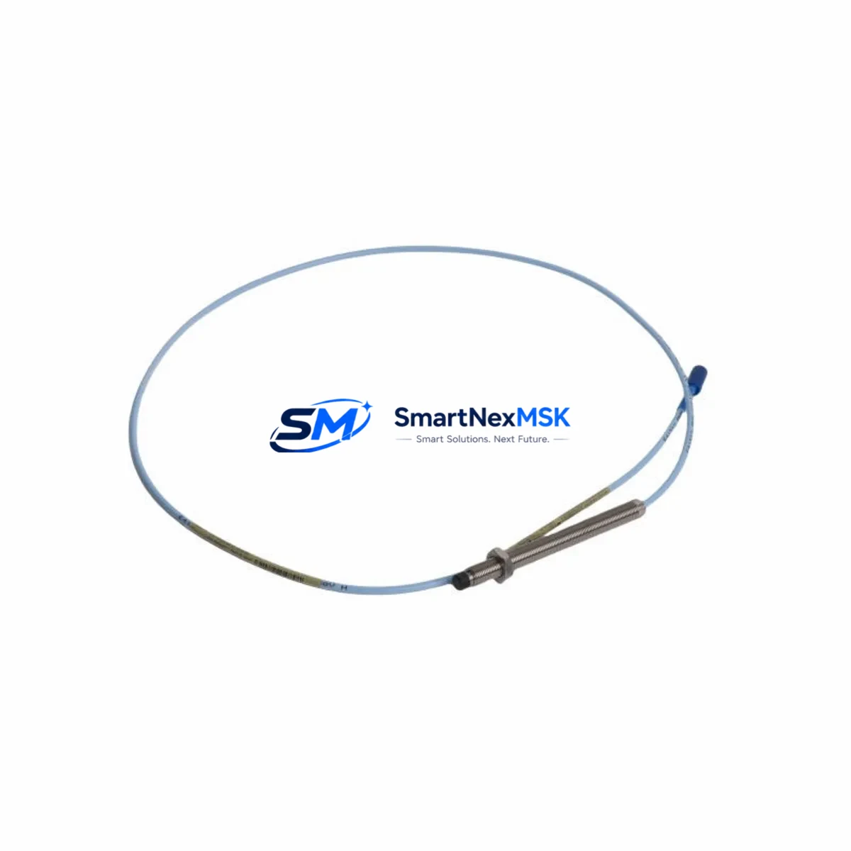
The Bently Nevada 330103-03-15-10-02-00 is an 8mm eddy-current proximity transducer engineered for the 3300 XL Series continuous vibration monitoring system. As a maintenance-ready original spare, this transducer is a critical component in rotating machinery protection programs across oil & gas, power generation, petrochemical, and heavy industrial facilities. When a vibration monitoring channel goes offline due to transducer failure, the risk of undetected shaft displacement, bearing wear, or rotor instability escalates rapidly — making fast, verified spare replacement essential to uptime and safety compliance.
Maintenance engineers and reliability teams rely on the 330103-03-15-10-02-00 to restore full-channel monitoring capability with minimal downtime. Its 8mm tip diameter, standard 5-metre extension cable compatibility, and -24 VDC bias voltage output make it a direct drop-in replacement within the 3300 XL architecture. Each unit shipped from SMARTNEXMSK undergoes pre-shipment functional verification and is backed by a 12-month warranty, ensuring confidence in both the component and the supply chain.
Spare Maintenance Table
| Parameter | Specification |
|---|---|
| Part Number / SKU | 330103-03-15-10-02-00 |
| Brand | Bently Nevada |
| Series | 3300 XL |
| Sensor Type | Eddy-Current Proximity Transducer |
| Tip Diameter | 8 mm |
| Cable Length | 1.5 m (integral) |
| Bias Voltage Output | -24 VDC (nominal) |
| Supply Voltage | -24 VDC |
| Sensitivity | 7.87 V/mm (200 mV/mil) |
| Linear Range | 0.25 mm – 2.25 mm (10–90 mil) |
| Operating Temperature | -35°C to +121°C |
| Compatibility | 3300 XL 8mm Proximitor Sensor, 3300 XL Monitor Series |
| Installation | M10 x 1 thread, bracket or direct mount |
| Application Environment | Turbines, compressors, pumps, motors — high-vibration industrial |
| Condition | Original, new or tested-serviceable |
| Pre-Shipment Test | Functional verification included |
| Warranty | 12 Months |
| Origin | USA |
Maintenance Planning for Continuous Operation
When replacing the 330103-03-15-10-02-00 in a 3300 XL monitoring loop, a thorough site inspection should extend beyond the transducer itself. Maintenance engineers should simultaneously inspect the 3300 XL Proximitor Sensor (typically the 330180 series) for housing cracks or contamination, and verify the 3300 XL extension cable (330130 series) for insulation damage, connector corrosion, or continuity loss — cable degradation is a leading cause of false gap readings that are often misattributed to transducer failure.
The 3300 XL monitor module (such as the 3300/16 or 3300/20 series) should be checked for alarm setpoint drift and channel configuration integrity after any transducer swap. If the control cabinet houses a Bently Nevada 3500 Series rack for critical machinery protection, verify that the 3500/42M or 3500/45 position monitor cards are reading within calibrated range following reinstallation. Power supply modules feeding the monitoring rack — including the 3500/15 Power Supply — should be load-tested to confirm stable -24 VDC output, as supply ripple directly affects transducer bias stability and gap measurement accuracy.
For facilities running integrated DCS or safety systems, confirm that the 4–20 mA output signal from the monitor is correctly received at the DCS I/O card or safety PLC input. Inspect terminal blocks and signal isolators in the marshalling cabinet for loose terminations or ground loops that could introduce noise into the vibration channel. Where the monitoring system interfaces with a System 1 Evolution software platform, verify that the channel tag, engineering units, and alarm thresholds are correctly mapped after the replacement. Spare inventory planning should also include 330103-00-08-10-02-00 (5mm variant) and 330103-05-30-10-02-00 (longer cable variant) to cover adjacent monitoring points in the same machinery train.
Site Replacement Workflow
Step 1 — Isolation & Permit: Obtain a work permit and isolate the monitoring channel at the 3300 XL monitor. Do not de-energize the full rack unless required — most 3300 XL monitors support hot-swap channel isolation via front-panel inhibit.
Step 2 — Gap Measurement & Documentation: Record the existing transducer gap voltage (target: -10 VDC ±0.5 VDC for most 8mm applications) before removal. This baseline confirms shaft position reference for post-installation verification.
Step 3 — Transducer Removal: Loosen the locknut (M10 x 1) and carefully back out the 330103-03-15-10-02-00 from its bracket. Inspect the probe tip for impact damage or shaft contact marks that may indicate a machinery event requiring further investigation.
Step 4 — Installation of Replacement: Thread the new 330103-03-15-10-02-00 to the correct gap distance. Use a non-contact gap meter or the monitor’s gap voltage display to set the gap to the specified linear midpoint. Torque the locknut to manufacturer specification and secure the cable with appropriate strain relief.
Step 5 — Functional Verification: Re-enable the monitor channel and confirm gap voltage, vibration baseline, and alarm status. Compare readings against adjacent channels and historical trend data in System 1 or the DCS historian to validate correct installation.
Step 6 — Documentation & Spare Replenishment: Update the CMMS work order with the replaced part number, installation date, and gap voltage reading. Immediately initiate a replenishment order for the consumed spare to maintain minimum stock levels for the machinery train.
Spare Parts Support FAQ
Q1: Is the 330103-03-15-10-02-00 compatible with both 3300 XL and legacy 3300 Series monitors?
The 330103-03-15-10-02-00 is designed and specified for the 3300 XL 8mm system. While the physical thread and gap range are similar to earlier 3300 Series transducers, sensitivity and scale factor specifications differ. Compatibility with legacy 3300 (non-XL) monitors should be verified against the monitor’s input specification sheet before installation. SMARTNEXMSK can provide technical documentation to support compatibility confirmation.
Q2: What pre-shipment testing is performed on each unit?
Every 330103-03-15-10-02-00 dispatched by SMARTNEXMSK undergoes functional verification including bias voltage output check, sensitivity confirmation, and cable continuity test. Units are individually packaged with anti-static protection and accompanied by a test record. This ensures the spare is field-ready upon arrival, minimizing installation risk during emergency replacement scenarios.
Q3: How should I manage spare inventory for a multi-train facility?
For facilities with 4 or more monitored machinery trains, a minimum of 2 units of the 330103-03-15-10-02-00 per site is recommended, supplemented by at least one spare Proximitor Sensor (330180 series) and one extension cable set (330130 series) per critical train. Planned maintenance intervals of 12–24 months provide a natural replenishment cycle. SMARTNEXMSK supports blanket order arrangements for facilities requiring guaranteed stock availability.
Q4: What is the warranty coverage and what does it include?
All units carry a 12-month warranty from the date of shipment, covering manufacturing defects and functional failure under normal operating conditions. Warranty claims are supported by SMARTNEXMSK’s technical team with replacement dispatch typically within 3 business days. The warranty does not cover damage resulting from incorrect installation, shaft contact, or operation outside specified environmental limits.
© 2026 SMARTNEXMSK. All rights reserved.
Original Source: https://smartnexmsk.com
Contact: sales@smartnexmsk.com | +86 18259474341


