Bently Nevada 330103-04-09-05-02-00 Retrofit-Ready Proximity Transducer for 3300 XL Control Systems
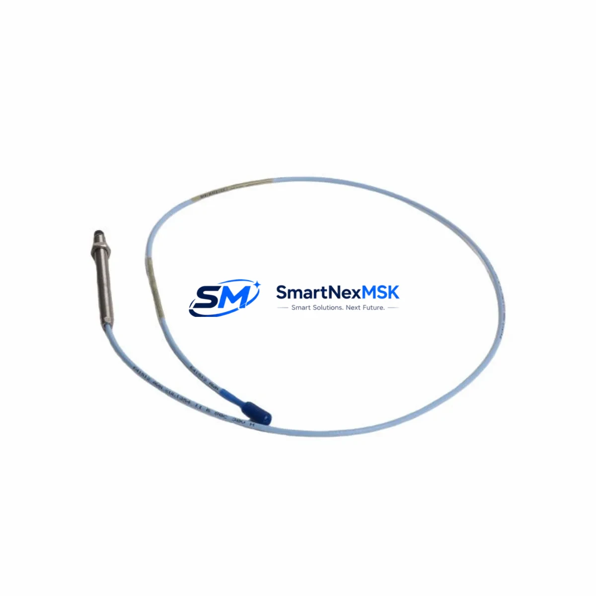
The Bently Nevada 330103-04-09-05-02-00 is a precision eddy-current proximity transducer engineered for the 3300 XL Series machinery protection platform. As legacy vibration monitoring systems reach end-of-life or face discontinued spare-parts availability, this module serves as a verified drop-in replacement and retrofit-ready upgrade for facilities operating rotating machinery — including turbines, compressors, pumps, and gearboxes — where continuous shaft monitoring is mission-critical.
This transducer operates within the 3300 XL system architecture, interfacing directly with the 3300 XL 8mm Extension Cable and the 3300 XL Proximitor Sensor to deliver calibrated gap voltage and dynamic vibration signals to the monitoring rack. When replacing an aging or failed unit, engineers must confirm the cable length configuration (standard 5-metre extension), the target material (steel or non-steel shaft), and the system’s existing gap voltage setpoint — typically –10 VDC at the nominal gap — before commissioning the replacement module.
Prior to installation, verify that the 3300 XL Monitor (such as the 3300/16 or 3300/20 series rack card) is configured to accept the correct transducer sensitivity factor (7.87 V/mm for standard steel targets). If the existing DCS or safety system — for example a Honeywell Experion PKS or an Emerson DeltaV — is receiving 4–20 mA retransmission signals from the monitor, those scaling parameters must be preserved in the controller configuration to avoid false alarms or spurious trips during the cutover window.
Upgrade Compatibility Table
| Parameter | 330103-04-09-05-02-00 (This Unit) | Notes / Retrofit Guidance |
|---|---|---|
| Series | Bently Nevada 3300 XL | Direct replacement within 3300 XL platform |
| Probe Tip Diameter | 8 mm | Confirm matching extension cable: 3300 XL 8mm |
| Cable Length | 5 m (extension) | Verify total system cable length ≤ 9 m |
| Sensitivity | 7.87 V/mm (200 mV/mil) | Match monitor card sensitivity setting |
| Gap Voltage (nominal) | –10 VDC | Re-gap after installation; confirm with oscilloscope |
| Target Material | AISI 4140 steel (standard) | Non-standard alloys require recalibration |
| Connector Interface | 3-pin MIL-spec | Compatible with standard 3300 XL Proximitor housing |
| Communication | Analog (gap voltage + dynamic) | No protocol migration required for 3300 XL rack |
| Replacement Scope | Drop-in for discontinued 330103 variants | Confirm suffix codes match application spec |
| Warranty | 12 Months | Covers manufacturing defects; includes pre-ship test report |
Retrofit Planning for Existing Automation Systems
Successful retrofit of the 330103-04-09-05-02-00 into an existing machinery protection system requires a structured pre-outage checklist. Begin by documenting the current wiring terminations at the 3300 XL Proximitor junction box and the corresponding monitor rack terminal block. The Proximitor sensor housing — typically mounted within 0.5 m of the bearing — must be inspected for corrosion or mechanical damage before the new transducer is seated.
In systems where the 3300 XL rack also hosts a 3300/55 Dual Voting Logic module or a 3300/46 Keyphasor module, confirm that the Keyphasor signal source and its gap voltage are unaffected by the transducer swap. If the control cabinet also contains a 3500 Series rack (Bently Nevada’s successor platform), this is an opportune moment to evaluate a phased migration path: the 3500/42M Proximitor I/O Module accepts the same 8 mm probe family and can be introduced alongside the existing 3300 XL infrastructure without a full cutover.
For facilities running a GE Mark VI or Woodward 505 turbine controller that relies on vibration trip signals from the 3300 XL monitor, coordinate the transducer replacement with the control room to place the relevant channel in bypass mode. This prevents a nuisance trip during the re-gapping procedure. Once the new 330103-04-09-05-02-00 is installed and the gap voltage is confirmed within the –10 ±0.5 VDC window, release the bypass and verify the dynamic signal on a portable ADRE Sxp data collector or equivalent spectrum analyser before returning the machine to service.
Where the existing system includes a 3300 XL 01 Power Supply or a 3300 XL 02 Dual Power Supply, check the available current budget on the Proximitor supply rail. Each 8 mm transducer system draws approximately 25 mA; adding a replacement unit to a partially loaded rack should remain well within the 500 mA rail capacity, but verification is mandatory in high-density installations.
Downtime Control During System Migration
Minimising unplanned downtime is the primary concern when replacing a proximity transducer on a running production line. The recommended approach is a cold-standby swap during a scheduled maintenance window: pre-configure the replacement 330103-04-09-05-02-00 on a bench fixture, confirm gap voltage and sensitivity against a calibration standard, and generate a pre-shipment test report before the unit reaches the field.
During the outage window, preserve the original PLC or DCS program logic — do not modify any vibration trip setpoints, time delays, or alarm thresholds until the new transducer has been validated in-situ. If the facility uses a Rockwell Automation ControlLogix or Siemens S7-400 safety controller that receives hardwired trip signals from the 3300 XL monitor, confirm that the safety function is in a defined safe state before disconnecting the transducer cable. Restore the safety function only after the new unit has passed the dynamic signal check.
For sites where continuous operation is required, a temporary wireless vibration monitor (such as a portable SKF Microlog or Emerson AMS 9420) can shadow the measurement point during the swap, providing an independent reference signal and ensuring that any anomalous vibration event is captured even while the permanent monitoring channel is offline.
Retrofit Support FAQ
Q1: Is the 330103-04-09-05-02-00 a direct replacement for other 330103 suffix variants?
A: The 330103 base part number covers a family of 8 mm proximity transducers differentiated by cable length, connector type, and temperature rating. The suffix codes (-04-09-05-02-00) specify a 5 m extension, standard temperature range, and MIL-spec connector. Before substituting a different suffix variant, verify that the cable length and connector configuration match your existing Proximitor housing and junction box wiring.
Q2: What commissioning steps are required after installation?
A: After mechanical installation, adjust the probe gap to achieve –10 VDC ±0.5 VDC on the Proximitor output. Confirm the dynamic signal is clean (low noise floor) using a spectrum analyser. Update the monitor rack’s channel configuration if the replacement unit has a different sensitivity factor than the original. Document the as-found and as-left gap voltage readings in the maintenance record.
Q3: How is wiring compatibility verified before the outage?
A: Compare the terminal block wiring diagram in the 3300 XL System Installation Manual (GEK-91555) against the replacement unit’s connector pinout. The standard 3-wire configuration (power, common, output) is consistent across the 330103 family, but confirm shield grounding practice matches the site’s EMC requirements to avoid introducing noise into the vibration signal chain.
Q4: What does the 12-month warranty cover?
A: The 12-month warranty covers manufacturing defects in materials and workmanship from the date of shipment. Each unit is pre-tested against Bently Nevada factory calibration standards and ships with a test report. Warranty claims require the original test report and a description of the failure mode; field-damaged units or those showing evidence of incorrect installation are evaluated on a case-by-case basis.
© 2026 SMARTNEXMSK. All rights reserved.
Original Source: https://smartnexmsk.com
Contact: sales@smartnexmsk.com | +86 18259474341


