Bently Nevada 330103-04-10-10-02-00 Retrofit-Ready Proximity Transducer for 3300 XL Control Systems
The Bently Nevada 330103-04-10-10-02-00 is an 8mm proximity transducer engineered for seamless integration into existing 3300 XL Series vibration monitoring systems. Whether you are replacing a discontinued unit, upgrading an aging control cabinet, or restoring a critical machine protection loop, this transducer delivers verified compatibility with the Bently Nevada 3300 XL signal conditioning architecture — minimizing retrofit risk and reducing unplanned downtime.
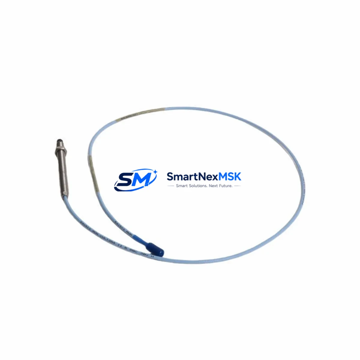
Designed for radial and axial shaft vibration measurement on rotating machinery including turbines, compressors, pumps, and motors, the 330103-04-10-10-02-00 maintains the same 8mm tip diameter, 5-metre integral cable configuration, and -24 VDC bias voltage output as the original factory specification. This ensures that existing field wiring, terminal block assignments, and monitor channel configurations remain fully intact during the swap-out procedure.
Upgrade Compatibility Table
| Parameter | 330103-04-10-10-02-00 Specification | Retrofit Notes |
|---|---|---|
| Tip Diameter | 8 mm | Direct drop-in; no bracket modification required |
| Cable Length | 5 m integral cable | Verify extension cable (330130-080-00-00) length matches original routing |
| Bias Voltage Output | -24 VDC nominal | Compatible with 3300 XL 8mm Proximitor® Sensor (330180-X1-05) |
| Sensitivity | 200 mV/mil (7.87 V/mm) | No rescaling required in 3500/40M or 3300 XL monitor |
| Target Material Compatibility | AISI 4140 steel (standard) | Confirm shaft material; non-standard alloys require gap recalibration |
| Connector / Termination | Integral coaxial, MIL-C-17 compatible | Mates directly with existing Proximitor® junction box wiring |
| Monitor Compatibility | 3300 XL, 3500 Series | Verify channel configuration in System 1 or 3500 Rack Configuration Software |
| Communication Protocol | Analogue 4–20 mA / voltage output | No protocol migration required; DCS/PLC input card unchanged |
| Installation Standard | API 670 compliant | Suitable for machinery protection on critical rotating equipment |
| Warranty | 12-Month Warranty | Covers manufacturing defects; includes pre-shipment functional test report |
Retrofit Planning for Existing Automation Systems
A successful retrofit of the 330103-04-10-10-02-00 begins well before the physical swap. Engineers should first audit the existing 3300 XL Proximitor® Sensor (typically a 330180-X1-05 or 330180-X1-CN variant) to confirm that the signal conditioner is still within calibration tolerance. If the Proximitor® is also degraded, replacing both the transducer and the Proximitor® simultaneously eliminates a second planned outage and is strongly recommended for critical machinery protection loops.
Next, review the terminal block wiring at the junction box. The 330103-04-10-10-02-00 uses a standard coaxial signal path: centre conductor carries the -24 VDC bias and the AC vibration signal, while the shield serves as the return. Confirm that the existing 330130-080-00-00 extension cable (or equivalent armoured coaxial extension) shows no shield continuity faults before reusing it. A damaged extension cable is a common source of noise and false alerts after transducer replacement.
For sites running a 3500 Series rack — including the 3500/40M Proximitor®/Seismic Monitor or the 3500/42M Proximitor®/Seismic Monitor — the channel configuration stored in the 3500 Rack Configuration Software must be verified against the new transducer’s sensitivity value. If the previous unit was a non-standard sensitivity variant, the software scale factor must be updated before the machine is returned to service. Similarly, any System 1 Evolution software trend templates or alarm setpoints referencing the old channel tag should be reviewed to ensure continuity of historical data.
Where the control system integrates vibration data into a DCS or safety PLC via a 4–20 mA analogue output card, the I/O channel scaling at the DCS input module should be confirmed unchanged. In Honeywell Experion or Emerson DeltaV environments, this typically means verifying the AI module engineering unit range and alarm deadband settings. No hardware changes to the DCS I/O rack are required for a like-for-like transducer replacement.
For facilities upgrading from older 3300 Series (non-XL) monitors to the 3300 XL platform as part of a broader control cabinet modernisation, the 330103-04-10-10-02-00 is fully compatible with the new monitor architecture. This migration path often involves replacing the 3300/16 or 3300/20 monitor cards with 3300 XL equivalents, updating the backplane wiring, and reconfiguring the rack power supply — typically a 3300/05 or equivalent — to support the revised channel count. The transducer itself requires no modification.
HMI screens in GE iFIX, Wonderware InTouch, or Siemens WinCC environments that display shaft vibration trends should be reviewed to confirm that the tag name and engineering unit mapping remain valid after the replacement. In most cases, because the 330103-04-10-10-02-00 is a direct drop-in replacement, no HMI reconfiguration is required. However, if the site is simultaneously migrating from a serial Modbus RTU communication link to Modbus TCP/IP or PROFIBUS DP, the HMI driver configuration will need to be updated independently of the transducer swap.
Downtime Control During System Migration
Minimising production downtime during a proximity transducer replacement requires a structured pre-outage preparation protocol. Before the planned maintenance window, the replacement 330103-04-10-10-02-00 should be bench-tested using a calibrated gap simulator to confirm bias voltage output (-24 VDC ±1 VDC at the nominal 1.0 mm gap) and sensitivity (200 mV/mil ±10%). This pre-shipment functional test is included with every unit supplied by SMARTNEXMSK and documented in the accompanying test report.
During the outage, the recommended sequence is: (1) isolate the monitor channel and place the 3500 or 3300 XL monitor into bypass mode to prevent spurious trips during the swap; (2) disconnect the extension cable at the junction box, not at the transducer tip, to avoid disturbing the probe mounting; (3) remove the old transducer and install the 330103-04-10-10-02-00, setting the gap to the machine OEM specification (typically 1.0–1.5 mm for most turbine and compressor shafts); (4) reconnect the extension cable and verify the bias voltage at the monitor input terminal before releasing the bypass.
This sequence preserves the original program logic in the safety PLC or DCS, maintains the existing alarm and trip setpoints, and ensures that the machine protection system is fully armed before the machine is restarted. For sites with redundant monitoring channels, the replacement can often be performed online on the standby channel, further reducing exposure to unprotected operation.
SMARTNEXMSK maintains in-stock inventory of the 330103-04-10-10-02-00 and related components to support emergency replacement scenarios. Standard lead time from order confirmation to dispatch is 1–3 business days, with expedited same-day dispatch available for critical outage situations. All units are supplied with a 12-month warranty covering manufacturing defects and include a pre-shipment functional test report.
Retrofit Support FAQ
Q1: Is the 330103-04-10-10-02-00 a direct replacement for the original Bently Nevada part of the same SKU?
Yes. The 330103-04-10-10-02-00 supplied by SMARTNEXMSK is a genuine or fully equivalent replacement that meets the original Bently Nevada factory specification for tip diameter, cable length, sensitivity, and bias voltage. It is compatible with the 3300 XL Proximitor® Sensor and the 3500 Series monitor rack without any hardware or software modification.
Q2: What wiring checks should be completed before installing the replacement transducer?
Before installation, verify the integrity of the 330130-080-00-00 extension cable using a continuity and insulation resistance test. Check the junction box terminal block for corrosion or loose connections. Confirm that the Proximitor® Sensor power supply voltage is within the -18 VDC to -24 VDC operating range. Any deviation should be corrected before the new transducer is connected.
Q3: Will the replacement transducer require recalibration of the 3500 or 3300 XL monitor?
For a like-for-like replacement (same SKU, same sensitivity), no monitor recalibration is required. The existing gap setting, alarm setpoints, and channel configuration remain valid. If the machine shaft has been re-machined or the target material has changed, a gap recalibration to the OEM specification is recommended before returning the machine to service.
Q4: What does the 12-month warranty cover, and is a test report included?
The 12-month warranty covers manufacturing defects in materials and workmanship from the date of shipment. It does not cover damage resulting from incorrect installation, overvoltage, or mechanical impact. Every unit is functionally tested prior to shipment, and a test report confirming bias voltage output and sensitivity is included in the packaging. For warranty claims, contact sales@smartnexmsk.com with the order reference and test report number.
© 2026 SMARTNEXMSK. All rights reserved.
Original Source: https://smartnexmsk.com
Contact: sales@smartnexmsk.com | +86 18259474341


