Bently Nevada 330103-05-12-10-02-00 Retrofit-Ready Proximity Transducer for 3300 XL Control Systems
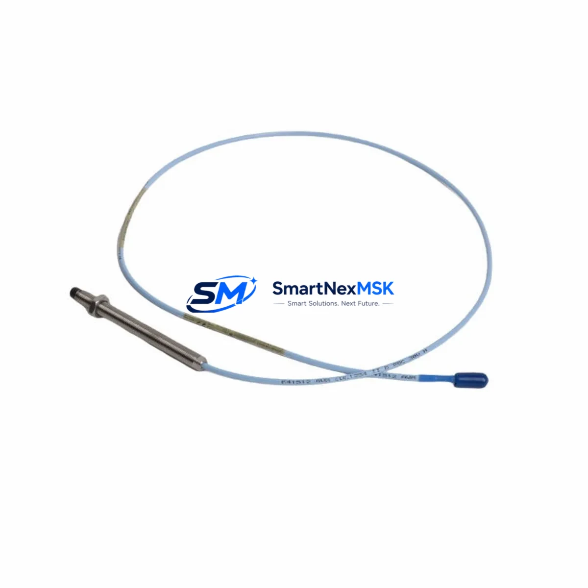
The Bently Nevada 330103-05-12-10-02-00 is a high-precision eddy-current proximity transducer engineered for the 3300 XL Series continuous machinery monitoring platform. As legacy 3300 Series installations reach end-of-service milestones, plant engineers and reliability teams are increasingly tasked with sourcing verified drop-in replacements that preserve existing wiring infrastructure, signal conditioning chains, and vibration monitoring logic without triggering a full system overhaul. This unit addresses exactly that requirement: a retrofit-ready transducer that integrates directly into existing 3300 XL monitor racks, extension cable assemblies, and proximitor driver circuits with no firmware modification or re-ranging required.
The 330103-05-12-10-02-00 operates on the standard Bently Nevada 3300 XL transducer system architecture, producing a linear DC output voltage proportional to the gap between the probe tip and the observed rotating shaft or target surface. The probe is factory-calibrated for use with the 3300 XL 8mm proximitor driver — typically the 330180 Series proximitor — and is designed to work within the standard -18 VDC to -24 VDC supply range common across 3300 XL monitor cards such as the 3300/16 and 3300/20 series. When replacing a failed or end-of-life transducer in an operating train, engineers should confirm that the existing extension cable — commonly the 330130 or 330140 Series armored extension cable — is undamaged and that the connector terminations are clean and torqued to specification before installing the new probe.
Retrofit planning for this transducer should begin with a review of the original installation drawing to confirm probe orientation, mounting thread size (5/16-24 UNF for this model), and the gap voltage setpoint recorded during the original commissioning. The 330103-05-12-10-02-00 uses a 5 mm probe tip diameter and is rated for a linear range of approximately 0.25 mm to 2.25 mm, consistent with the standard 3300 XL 8mm system calibration curve. If the existing proximitor driver — such as the 330180-51-00 or 330180-90-00 — shows signs of drift or output instability, it is advisable to replace the proximitor simultaneously to ensure the transducer system performs within the ±0.5% full-scale linearity specification required for API 670-compliant vibration monitoring.
Upgrade Compatibility Table
| Parameter | 330103-05-12-10-02-00 (This Unit) | Notes / Retrofit Guidance |
|---|---|---|
| Series Compatibility | Bently Nevada 3300 XL | Direct replacement for 3300 XL 8mm transducer system |
| Probe Tip Diameter | 5 mm (8mm body) | Verify mounting hole clearance before installation |
| Thread Size | 5/16-24 UNF | Match to existing bracket; re-tap if thread is damaged |
| Linear Range | 0.25 – 2.25 mm | Set gap to midpoint (~1.25 mm) per original commissioning record |
| Supply Voltage | -18 VDC to -24 VDC | Confirm monitor card output rail before powering |
| Output Sensitivity | 7.87 V/mm (200 mV/mil) | Matches 3300 XL standard calibration; no re-ranging needed |
| Compatible Proximitor | 330180 Series | Replace proximitor if output drift exceeds ±1% FS |
| Compatible Extension Cable | 330130 / 330140 Series | Inspect armored jacket and connector pins before reuse |
| Monitor Card Compatibility | 3300/16, 3300/20 Series | No firmware or scaling change required |
| Communication Protocol | Analog (4–20 mA / DC voltage) | No protocol migration required for 3300 XL platform |
| Installation Standard | API 670 4th / 5th Edition | Verify overall system compliance after replacement |
| Warranty | 12 Months | Covers manufacturing defects; includes pre-shipment functional test |
Retrofit Planning for Existing Automation Systems
When integrating the 330103-05-12-10-02-00 into an existing machinery protection system, the retrofit scope typically extends beyond the transducer itself. A complete 3300 XL transducer system consists of three interdependent components: the probe, the extension cable, and the proximitor driver. In most field replacement scenarios, the 330130-10-00 or 330140-10-00 armored extension cable is reused if it passes a continuity and insulation resistance check. The 330180 Series proximitor — mounted in the field junction box or directly on the monitor rack — should be inspected for output voltage stability under a known gap condition before the new probe is declared operational.
For installations where the 3300 XL monitor rack itself is aging, this transducer replacement is often the first step in a phased upgrade toward the System 1 Evolution platform or the 3500 Series machinery protection system. In such cases, the 3500/42M position monitor or the 3500/40M proximitor I/O module may be specified as the eventual target hardware, and the transducer replacement provides an opportunity to document current gap voltages, alarm setpoints, and danger thresholds before the monitor migration begins. Engineers should capture all channel configuration data from the existing 3300/16 or 3300/20 monitor cards using the Rack Configuration Software (RCS) before decommissioning any hardware.
In control cabinet environments where the 3300 XL rack shares a backplane with other I/O modules — such as the 3300/55 tachometer input module or the 3300/65 temperature monitor — care must be taken to isolate only the affected channel during transducer replacement. The 3300 XL rack uses a modular card architecture that allows individual monitor cards to be removed without powering down the entire rack, provided the system is configured for hot-swap operation. Confirm this capability with the site’s DCS or safety system integrator before proceeding with a live replacement. If the plant runs a Honeywell Experion PKS or Emerson DeltaV distributed control system, verify that the vibration channel alarm suppression is activated in the DCS historian before pulling the transducer to avoid spurious trip signals propagating to the safety instrumented system.
For facilities operating older Bently Nevada 3300 Series (non-XL) racks, the 330103-05-12-10-02-00 is not a direct replacement without a proximitor system change. In those cases, the migration path typically involves replacing the 3300 Series proximitor with a 3300 XL-compatible 330180 unit and verifying that the monitor card accepts the updated output range. Document all wiring changes in the as-built drawings and update the P&ID markups accordingly before closing out the work order.
Downtime Control During System Migration
Minimizing unplanned downtime during a proximity transducer replacement requires a structured pre-outage preparation protocol. Before the maintenance window opens, the technician should have the replacement 330103-05-12-10-02-00 bench-tested against a known target at the specified gap distance to confirm output voltage matches the calibration certificate. A calibrated gap tool or feeler gauge set should be staged at the work site along with the original commissioning gap voltage record.
During the replacement, the existing program logic in the plant’s safety PLC or DCS — whether running on a Rockwell Automation ControlLogix platform, a Siemens S7-400H redundant controller, or an ABB AC800M process controller — should have the affected vibration channel placed in bypass or maintenance override mode. This prevents a nuisance trip from the open-circuit condition that occurs when the transducer connector is disconnected. The bypass should be logged in the plant’s permit-to-work system and cleared immediately after the new transducer is gapped, connected, and verified to be producing a stable output within the expected linear range.
After installation, the gap voltage should be recorded and compared to the original commissioning value. If the new reading differs by more than ±0.1 VDC from the historical baseline, the probe position should be adjusted before the bypass is cleared. Once the channel is restored to normal monitoring mode, observe the vibration trend for a minimum of one full machine start-up cycle to confirm that the signal is stable, that the alarm and danger setpoints are responding correctly, and that the DCS historian is logging the channel without data quality flags. This end-to-end verification step is the most effective way to confirm that the retrofit has been completed successfully without introducing new failure modes into the machinery protection chain.
Retrofit Support FAQ
Q: Is the 330103-05-12-10-02-00 a direct drop-in replacement for the original Bently Nevada part of the same number?
A: Yes. This unit is manufactured to the same dimensional, electrical, and calibration specifications as the original Bently Nevada 330103-05-12-10-02-00. It is compatible with the 3300 XL 8mm transducer system, including the 330180 Series proximitor and 330130/330140 Series extension cables, with no modification required.
Q: What pre-shipment testing is performed on this transducer?
A: Each unit undergoes a functional output test at a calibrated gap distance to verify sensitivity (7.87 V/mm), linearity across the full measurement range, and supply current draw within specification. A test report is available upon request. All units are covered by a 12-month warranty against manufacturing defects from the date of shipment.
Q: Can this transducer be used with a 3300 Series (non-XL) proximitor?
A: The 330103-05-12-10-02-00 is optimized for the 3300 XL system. Use with a legacy 3300 Series proximitor may result in output scaling differences. We recommend replacing the proximitor with a 330180 Series unit when migrating from a non-XL rack to ensure full system calibration compliance.
Q: How should I handle wiring during the replacement to avoid signal errors?
A: Disconnect the extension cable from the proximitor first, then remove the probe from the mounting bracket. Inspect the extension cable connector pins for corrosion or mechanical damage before reuse. Reconnect in reverse order, torque the probe locknut to the specified value, set the gap using a feeler gauge, and verify output voltage before restoring the channel to active monitoring. Record all as-found and as-left gap voltages in the maintenance log.
© 2026 SMARTNEXMSK. All rights reserved.
Original Source: https://smartnexmsk.com
Contact: sales@smartnexmsk.com | +86 18259474341


