Bently Nevada 330103-05-12-10-02-CN 3300 XL Maintenance-Ready Spare: Spare Parts Replacement and Industrial Downtime Risk Control
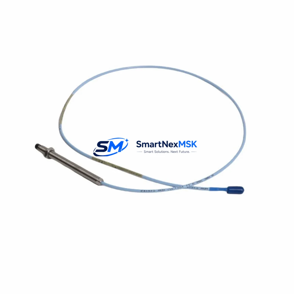
The Bently Nevada 330103-05-12-10-02-CN is an 8mm proximity transducer probe designed for use within the 3300 XL Proximity Transducer System — one of the most widely deployed vibration and position monitoring platforms in rotating machinery protection. This component serves as a direct-contact sensing element in turbine, compressor, pump, and motor protection circuits, providing continuous shaft displacement and vibration data to the monitoring system. When this probe degrades or fails, the entire protection loop is compromised, creating an immediate risk of undetected machinery fault and unplanned shutdown.
For maintenance engineers managing aging turbomachinery or DCS-integrated protection systems, maintaining a verified spare of the 330103-05-12-10-02-CN is a fundamental element of any predictive maintenance or reliability-centered maintenance (RCM) program. The -CN suffix designates the cable length and connector configuration, making exact SKU matching critical — substituting an incorrect cable length or connector type will result in signal loss, impedance mismatch, or physical incompatibility with the junction box or proximitor housing.
This listing supplies an original Bently Nevada 330103-05-12-10-02-CN probe, sourced from authorized distribution channels, pre-shipment tested for output voltage linearity and gap sensitivity, and backed by a 12-month warranty covering manufacturing defects and functional performance.
Spare Maintenance Table
| Parameter | Specification |
|---|---|
| SKU / Part Number | 330103-05-12-10-02-CN |
| Brand | Bently Nevada (Baker Hughes) |
| Series | 3300 XL Proximity Transducer System |
| Probe Diameter | 8mm |
| Sensing Range | 0–2.54 mm (0–100 mil) |
| Output Sensitivity | 7.87 V/mm (200 mV/mil) |
| Operating Temperature | -35°C to +177°C (probe tip) |
| Supply Voltage | -24 VDC (via proximitor/driver) |
| Compatibility | 3300 XL Proximitor (330180 series), API 670 4th/5th Ed. |
| Cable Length | 5m (extension cable included per -05-12 designation) |
| Connector Type | CN (standard coaxial, field-replaceable) |
| Installation | Threaded probe tip, jam-nut mount, radial or axial orientation |
| Application Environment | Turbines, compressors, pumps, motors — oil & gas, power generation, petrochemical |
| Maintenance Recommendation | Replace at first sign of output drift >±5%; inspect every 12–18 months |
| Condition | Original, new-in-box, pre-shipment tested |
| Warranty | 12 months from date of shipment |
Maintenance Planning for Continuous Operation
When replacing the 330103-05-12-10-02-CN probe in the field, a disciplined maintenance engineer will not stop at the probe itself. The 3300 XL system is a tightly coupled measurement chain, and degradation in any upstream or downstream component can mask or mimic a probe fault — or cause a new fault immediately after probe replacement.
Begin by inspecting the 330180-91-00 Proximitor/Evolver module paired with this probe. The proximitor supplies the -24 VDC oscillator signal and converts the probe’s eddy-current response into a DC voltage output. A worn or contaminated proximitor will produce erratic gap voltage even with a new probe installed. Check the output voltage at the recommended air gap (typically 1.27 mm / 50 mil) and confirm it falls within the ±0.5 V tolerance band.
Next, verify the 3300/16 Power Supply module or equivalent rack power supply feeding the monitoring rack. Voltage sag or ripple on the -24 VDC rail is a common root cause of false vibration alarms and should be measured with a calibrated multimeter before and after probe replacement. If the rack uses a 3500/15 Power Supply in a 3500 series migration environment, confirm cross-compatibility of the supply rail.
Inspect all extension cables in the signal path — particularly the 330130-series armored extension cables connecting the probe to the proximitor. Cracked insulation, corroded BNC connectors, or kinked cable runs will introduce noise into the vibration signal and should be replaced as a set with the probe during planned outages.
For installations near high-EMI environments (variable frequency drives, large motors, or arc furnaces), check whether signal isolators or conditioners are installed between the proximitor output and the DCS or safety system input. Devices such as the Bently Nevada 3300/55 or equivalent DIN-rail signal isolators should be inspected for output drift and recalibrated if the probe replacement does not resolve alarm conditions.
Review the terminal blocks and I/O wiring in the junction box and monitoring rack. Loose terminations on the signal pair (typically labeled SIG and COM) are a frequent source of intermittent faults that are misdiagnosed as probe failures. Torque all terminals to specification and inspect for corrosion, especially in humid or offshore environments.
If the machine is also monitored for axial position (thrust), confirm that the companion 330103-series axial probe and its proximitor are also within calibration. Radial and axial probes in the same protection loop should be replaced or recalibrated together during major overhauls to maintain system-level accuracy.
Finally, if the plant is running a System 1 Evolution or Orbit 60 condition monitoring platform, update the probe configuration in the software after replacement to reflect the new probe serial number and recalibration date. This ensures the historian and alarm management system reflect accurate baseline data going forward.
Site Replacement Workflow
Step 1 — Isolation and Permit: Obtain a hot-work or cold-work permit as required by site safety procedures. Isolate the monitoring channel at the rack (do not de-energize the entire rack unless required) to avoid triggering a spurious trip during probe removal.
Step 2 — Gap Measurement (Before Removal): Record the existing air gap voltage from the proximitor output terminal. This baseline confirms whether the old probe was within range or had already drifted, and provides a reference for the new probe setup.
Step 3 — Probe Removal: Loosen the jam nut and carefully back out the probe from the bracket. Inspect the probe tip for physical damage, pitting, or contamination. Inspect the target area on the shaft for runout, scratches, or buildup that could affect the new probe’s reading.
Step 4 — New Probe Installation: Thread the 330103-05-12-10-02-CN into the bracket. Set the air gap to the manufacturer-specified value (typically 1.27 mm / 50 mil for 8mm probes) using a feeler gauge or the voltage method. Tighten the jam nut to the specified torque.
Step 5 — Signal Verification: Reconnect the extension cable and proximitor. Power up the channel and verify the output voltage at the set gap. Confirm the reading is within the linear range and matches the calibration curve for the 330103 probe family.
Step 6 — System Restore and Documentation: Remove the channel isolation, restore normal monitoring, and document the replacement in the CMMS (Computerized Maintenance Management System) with the new probe serial number, installation date, and gap voltage reading. Schedule the next inspection interval per the plant’s RCM plan.
This workflow minimizes downtime, ensures system compatibility, and creates a traceable maintenance record that supports both regulatory compliance and future fault analysis.
Spare Parts Support FAQ
Q1: Is the 330103-05-12-10-02-CN a direct replacement for older 330103 variants with different cable lengths?
The -05-12 designation specifies a 5-meter probe-to-proximitor cable assembly. Substituting a different cable length (e.g., -03-12 or -08-12) will change the system’s total electrical length and may shift the calibration curve. Always match the exact SKU when replacing in an existing installation. If the original cable length is unknown, measure the installed cable or consult the original engineering drawing before ordering.
Q2: How should this spare be stored before installation?
Store the 330103-05-12-10-02-CN in its original packaging in a dry, temperature-controlled environment (10°C–40°C, <85% RH non-condensing). Avoid storing near strong magnetic fields or high-vibration areas. The probe tip is sensitive to physical impact — do not remove the protective cap until installation. Shelf life under proper storage conditions is typically 3–5 years; inspect the cable insulation and connector before installation if stored for more than 2 years.
Q3: What pre-shipment testing is performed on this unit?
Each 330103-05-12-10-02-CN supplied by SMARTNEXMSK is tested for DC output voltage at the standard air gap, cable continuity and insulation resistance, connector integrity, and physical dimensional compliance. A test report is available upon request. Units that do not meet Bently Nevada’s published specifications are not shipped.
Q4: What does the 12-month warranty cover?
The 12-month warranty covers manufacturing defects, functional performance failure under normal operating conditions, and any deviation from the published Bently Nevada 330103 series specifications. It does not cover damage resulting from incorrect installation, overvoltage, physical impact, or use outside the specified environmental range. Warranty claims are processed within 5 business days of receipt of the returned unit, with replacement or full refund at the customer’s option.
© 2026 SMARTNEXMSK. All rights reserved.
Original Source: https://smartnexmsk.com
Contact: sales@smartnexmsk.com | +86 18259474341


