Bently Nevada 330103-06-10-10-02-05 Retrofit-Ready Proximity Transducer for 3300 XL Control Systems
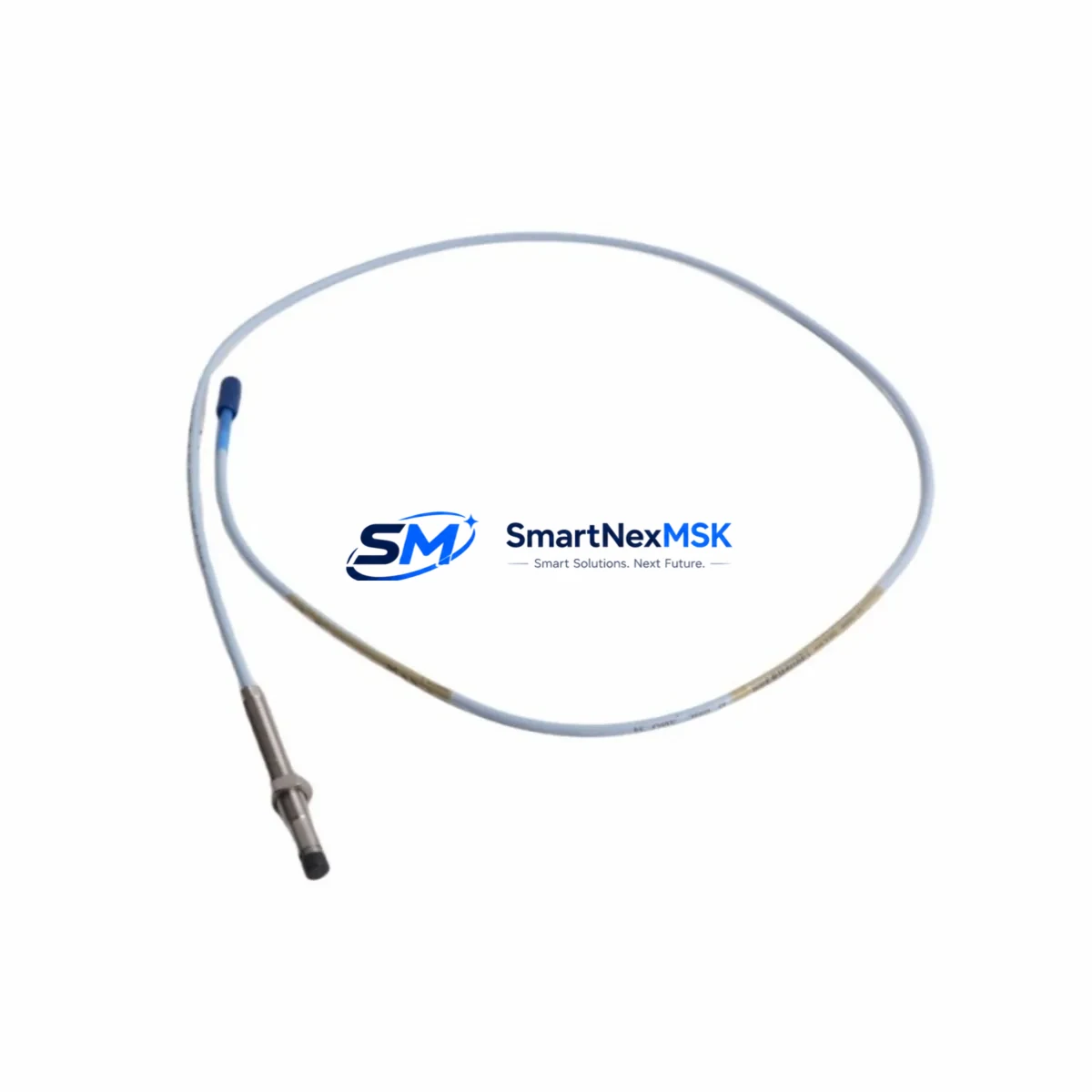
The Bently Nevada 330103-06-10-10-02-05 is an 8mm eddy-current proximity transducer engineered for the 3300 XL Series machinery protection platform. As legacy 3300 XL installations approach end-of-support milestones, plant engineers and reliability teams are actively sourcing verified drop-in replacements that preserve existing wiring infrastructure, maintain signal chain integrity, and eliminate the need for full panel redesigns. This unit is stocked, tested, and ready for immediate dispatch to support planned turnarounds, emergency spares programs, and phased control-system modernization projects.
Whether you are replacing a failed transducer on a critical rotating machine, building out a spare-parts buffer for an aging 3300 XL rack, or executing a broader migration from a legacy Bently Nevada 3300 Series platform to a current-generation System 1 condition monitoring architecture, the 330103-06-10-10-02-05 provides a technically sound, cost-effective solution that minimizes engineering rework and field commissioning time.
Upgrade Compatibility Table
| Parameter | Detail |
|---|---|
| SKU / Part Number | 330103-06-10-10-02-05 |
| Brand | Bently Nevada |
| Series Compatibility | 3300 XL 8mm Proximity Transducer System |
| Probe Diameter | 8 mm |
| Cable Length | 1.0 m integral cable (extension cable ordered separately) |
| Extension Cable Compatibility | 330130 Series extension cables (3 m, 5 m, 9 m options) |
| Driver / Proximitor Compatibility | 3300 XL 8mm Proximitor Sensor (330180 Series) |
| Connector Type | Standard BNC / coaxial per 3300 XL wiring spec |
| Installation Interface | Direct replacement — no bracket modification required for standard 3300 XL mounting |
| Signal Output | –24 VDC bias, linear range per 3300 XL calibration curve |
| Communication / Protocol | Analog voltage output; compatible with 3300 XL monitor cards and System 1 data acquisition |
| Replacement Recommendation | Direct drop-in for 330103-06-10-10-02-05; verify gap voltage at commissioning |
| Commissioning Focus | Gap voltage setting, polarity check, cable continuity, Proximitor bias verification |
| Warranty | 12 Months — covers manufacturing defects and signal performance |
Retrofit Planning for Existing Automation Systems
A successful retrofit of the 330103-06-10-10-02-05 begins well before the maintenance window opens. The first step is a full audit of the existing 3300 XL rack configuration. Most installations pair this transducer with a 330180 Series Proximitor Sensor mounted in a field junction box, connected via a 330130 Series extension cable routed back to the monitor rack. Before ordering, confirm the extension cable length — 3 m, 5 m, or 9 m — so the replacement assembly arrives as a matched set and no field splicing is required.
Inside the control cabinet, the 3300 XL monitor cards — typically a 3300/16 or 3300/20 Series vibration monitor — receive the analog voltage signal from the Proximitor. These cards should be inspected for firmware revision and calibration status during the same outage window. If the plant is running a parallel migration to a newer Bently Nevada 3500 Series rack, note that the 3500/42M position monitor accepts the same eddy-current transducer family, which simplifies the transition and allows the 330103-06-10-10-02-05 to remain in service during a phased rack upgrade.
Power supply integrity is a frequently overlooked factor in proximity transducer retrofits. The 3300 XL Proximitor requires a stable –24 VDC supply, typically sourced from a dedicated power supply module within the 3300 XL rack. Verify supply voltage under load before installing the replacement transducer; a marginal power supply will produce erratic gap readings and false alerts even with a new probe. If the power supply module is original equipment from the early installation, consider replacing it concurrently to avoid a repeat outage.
For plants operating Bently Nevada System 1 software for condition monitoring and trending, the replacement transducer integrates without software reconfiguration provided the Proximitor model and cable assembly remain within the original calibration family. System 1 channel configuration — including full-scale range, alert setpoints, and danger thresholds — is stored at the monitor card level and is preserved through a transducer swap. However, if the site is also upgrading from an older System 1 version to the current Evolution platform, a channel re-verification step should be included in the commissioning checklist.
In applications where the 330103-06-10-10-02-05 is used for axial position measurement on steam turbines or compressors, the replacement procedure must include a cold-position gap check against the original installation record. Axial position channels feeding a 3300/55 Series thrust monitor are safety-critical; any deviation from the original gap voltage baseline must be documented and approved before the machine is returned to service. Coordinate with the OEM or a certified machinery protection engineer if the original installation records are unavailable.
Downtime Control During System Migration
Minimizing unplanned downtime during a proximity transducer replacement requires a structured pre-outage preparation protocol. Begin by downloading and archiving the current System 1 configuration database and all monitor card parameter files before the maintenance window. This ensures that if a monitor card requires replacement or reset during the outage, the original setpoints, scaling factors, and alarm logic can be restored in minutes rather than hours.
During the physical swap, keep the original 330103-06-10-10-02-05 assembly intact until the replacement unit has been bench-verified for bias voltage and cable continuity. Use a calibrated Proximitor test kit to confirm the replacement transducer produces the correct output voltage at the nominal air gap before installation in the machine. This pre-installation check eliminates the most common cause of extended commissioning time — discovering a wiring or calibration issue only after the machine has been reassembled.
Once the replacement transducer is installed and the gap is set, perform a slow-roll check at the earliest opportunity to verify vibration baseline and position readings against historical trend data in System 1. If the readings fall within the expected band, the channel can be returned to normal monitoring mode and the machine cleared for restart. Document the as-found and as-left gap voltages, cable serial numbers, and Proximitor bias readings in the plant maintenance management system to support future reliability analysis and spare-parts planning.
For sites managing multiple 3300 XL racks across a facility, a rolling replacement strategy — addressing one rack per planned outage cycle — allows the plant to systematically refresh aging transducer assemblies without concentrating risk in a single extended shutdown. Pair each transducer replacement with a review of the associated extension cable condition; cables exposed to high-temperature or high-vibration environments degrade faster than the transducer itself and are a common source of intermittent signal faults.
Retrofit Support FAQ
Q: Is the 330103-06-10-10-02-05 a direct replacement for the original Bently Nevada part, or are there wiring differences I need to account for?
A: This unit is a direct drop-in replacement for the original 330103-06-10-10-02-05. The connector, cable diameter, and signal characteristics are identical to the factory specification. No wiring modifications are required at the junction box or monitor card terminal strip. Confirm the extension cable connector seating and torque the probe lock nut to the specified value during installation.
Q: What commissioning steps are required after installing the replacement transducer?
A: Set the air gap to the value specified in the original installation record (typically 1.0 mm for an 8mm probe on a steel target). Measure the Proximitor output voltage with a calibrated multimeter and confirm it falls within the linear range defined in the 3300 XL calibration curve. Verify cable continuity from the probe tip to the monitor card input terminal. Perform a slow-roll vibration check and compare readings to the historical baseline in System 1 before returning the channel to normal monitoring.
Q: Can this transducer be used with a 3500 Series rack if we are migrating from 3300 XL?
A: Yes. The 330103-06-10-10-02-05 is compatible with 3500 Series Proximitor Sensors and monitor cards that accept the 8mm eddy-current transducer family. During migration, the transducer and extension cable assembly can remain in place while the Proximitor and monitor card are upgraded, reducing field work to the junction box and rack connections only. Verify the 3500 Series channel configuration matches the original calibration parameters before enabling monitoring.
Q: What does the 12-month warranty cover, and what is the shipping lead time?
A: The 12-month warranty covers manufacturing defects and signal performance under normal operating conditions. Units are inspected and function-tested prior to dispatch. Standard lead time is 1–3 business days for in-stock units, with expedited shipping available for emergency requirements. Contact our team with your plant location and urgency level to confirm the fastest available routing.
© 2026 SMARTNEXMSK. All rights reserved.
Original Source: https://smartnexmsk.com
Contact: sales@smartnexmsk.com | +86 18259474341


