Bently Nevada 330103-06-10-50-02-00 Spare 3300 XL: Precision Spare for Vibration Monitoring Downtime Recovery
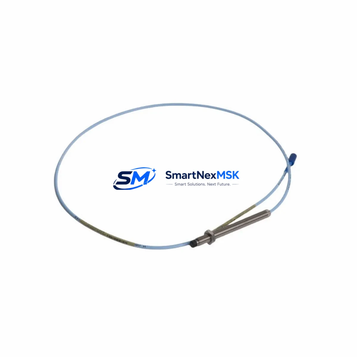
The Bently Nevada 330103-06-10-50-02-00 is an original 8mm proximity transducer engineered for the 3300 XL Series continuous vibration monitoring system. In rotating machinery protection environments — turbines, compressors, pumps, and gearboxes — this transducer serves as the primary sensing element for shaft radial vibration, axial position, and differential expansion measurement. When this component fails or degrades, the entire protection loop is compromised, triggering unplanned shutdowns and exposing critical assets to mechanical damage.
Sourced as a genuine original spare, the 330103-06-10-50-02-00 is tested prior to shipment and backed by a 12-month warranty. Stocking this SKU as a ready-to-deploy spare is the most effective strategy for minimizing mean time to repair (MTTR) in facilities running Bently Nevada 3300 XL protection systems.
Spare Maintenance Table
| Parameter | Specification |
|---|---|
| SKU / Part Number | 330103-06-10-50-02-00 |
| Brand | Bently Nevada |
| Series | 3300 XL |
| Product Type | 8mm Proximity Transducer |
| Sensing Range | 0–2.54 mm (0–100 mil) |
| Output Sensitivity | 7.87 V/mm (200 mV/mil) |
| Supply Voltage | –24 VDC (nominal) |
| Cable Length | 5.0 m (standard extension) |
| Connector Type | 3-pin MIL-C-5015 compatible |
| Temperature Range | –35°C to +121°C (operating) |
| Target Material Compatibility | Steel, Inconel, 4140 alloy |
| Ingress Protection | IP67 (sealed housing) |
| Compatibility | 3300 XL 8mm Proximitor Sensor, 3300 XL Monitor Series |
| Application | Radial vibration, axial position, differential expansion |
| Origin | USA (Original Bently Nevada) |
| Warranty | 12 Months |
| Condition | New / Tested before shipment |
Maintenance Planning for Continuous Operation
Replacing the 330103-06-10-50-02-00 transducer is rarely an isolated task. Maintenance engineers performing a planned or emergency replacement should treat this as an opportunity to inspect and verify the entire proximity measurement chain and associated protection loop components.
Begin with the 3300 XL 8mm Proximitor Sensor (e.g., 330180-X1-05), which conditions the transducer signal and must be gap-calibrated to match the replacement transducer’s sensitivity curve. A mismatched or aged Proximitor will produce erroneous vibration readings even with a new transducer installed. Next, verify the 3300 XL Monitor (such as the 3300/16 or 3300/20 series) for firmware version compatibility and channel configuration — particularly if the replacement transducer has a different cable length or sensitivity code suffix.
Inspect the extension cable (typically 330130-series) for insulation damage, connector corrosion, and continuity. A degraded cable is a common root cause of intermittent vibration signal faults that are misdiagnosed as transducer failure. Check the junction box terminal blocks and cable gland seals for moisture ingress, especially in outdoor or wash-down environments.
At the rack level, inspect the 3300 XL Power Supply module for output voltage stability — the –24 VDC rail must be within ±1% for accurate transducer operation. If the facility uses a Bently Nevada 3500 Series rack alongside the 3300 XL system, verify that shared power distribution panels and I/O terminal boards (3500/92 or equivalent) are not introducing ground loops that could corrupt the proximity signal.
For facilities with integrated DCS or safety systems, confirm that the 4–20 mA output signal from the monitor is correctly received at the DCS I/O card or safety PLC input module after replacement. Signal isolators or Zener barriers in hazardous-area installations should be tested for correct clamping voltage and loop resistance. Finally, review the HMI trend display for the affected channel to confirm baseline vibration levels are restored to pre-fault values after installation and gap setting.
Stocking the 330103-06-10-50-02-00 alongside its Proximitor sensor, a spare extension cable set, and a calibrated gap tool ensures that any future replacement can be completed within a single maintenance window, minimizing production loss.
Site Replacement Workflow
Step 1 — Isolation & Permit: Obtain a work permit and isolate the monitor channel. Note the current gap voltage (typically –10 to –18 VDC) and vibration baseline from the HMI or DCS historian before de-energizing.
Step 2 — Transducer Removal: Disconnect the extension cable at the junction box. Unthread the transducer from the mounting bracket using the correct spanner. Record the installed gap distance (number of turns from contact).
Step 3 — Inspection: Inspect the probe tip for target material buildup, pitting, or physical damage. Clean the mounting threads and verify the bracket is undamaged and properly grounded.
Step 4 — Installation of 330103-06-10-50-02-00: Thread the replacement transducer to the same gap distance as the removed unit (typically 1.0–1.5 mm / 40–60 mil for steel targets). Connect the extension cable and verify connector seating.
Step 5 — Gap Calibration: Power the Proximitor and measure the DC gap voltage. Adjust the transducer position until the gap voltage falls within the linear range specified on the calibration chart for the 330103-06-10-50-02-00 / 330180 Proximitor pair. Lock the transducer with the locknut.
Step 6 — Functional Verification: Restore the monitor channel and confirm the vibration reading on the HMI is within expected baseline range. Check for alarm or danger setpoint trips. Log the replacement in the maintenance management system (CMMS) with the new transducer serial number.
This workflow is compatible with legacy 3300 XL installations and supports seamless migration from older 3300 Series (non-XL) transducers where physical dimensions and thread pitch are equivalent, avoiding the need for bracket modifications and reducing downtime to under two hours for experienced technicians.
Spare Parts Support FAQ
Q1: Is the 330103-06-10-50-02-00 compatible with both 3300 and 3300 XL monitors?
The 330103-06-10-50-02-00 is designed and calibrated for the 3300 XL 8mm Proximitor system. It is physically compatible with earlier 3300 Series brackets and mounting hardware, but sensitivity and gap calibration must be verified against the specific Proximitor sensor in use. Always confirm the Proximitor model suffix matches the transducer sensitivity code before installation.
Q2: What is included in the 12-month warranty and how is it applied?
Every 330103-06-10-50-02-00 unit shipped by SMARTNEXMSK is tested for output sensitivity, insulation resistance, and connector integrity prior to dispatch. The 12-month warranty covers manufacturing defects and out-of-specification performance under normal operating conditions. Warranty claims are supported with a replacement unit dispatched upon receipt and inspection of the returned part.
Q3: How should this transducer be stored as a long-term spare?
Store the 330103-06-10-50-02-00 in its original packaging in a dry, temperature-controlled environment (10°C–35°C, <70% RH non-condensing). Avoid storing near strong magnetic fields or solvents. Inspect the probe tip and connector annually. For facilities with extended outage cycles, SMARTNEXMSK recommends maintaining a minimum of two units per critical machine train to ensure immediate availability during both planned and emergency maintenance events.
Q4: Can SMARTNEXMSK supply the complete 3300 XL proximity measurement chain?
Yes. SMARTNEXMSK maintains inventory of the full 3300 XL measurement chain including the 330103-series transducers, 330130-series extension cables, 330180-series Proximitor sensors, and 3300 XL monitor modules. Multi-component orders are tested as a matched set where requested, and consolidated shipment reduces lead time for complete loop replacements. Contact sales@smartnexmsk.com for availability and lead time confirmation.
© 2026 SMARTNEXMSK. All rights reserved.
Original Source: https://smartnexmsk.com
Contact: sales@smartnexmsk.com | +86 18259474341


