Bently Nevada 330103-06-16-10-02-00 Retrofit-Ready Proximity Transducer for 3300 XL Control Systems
The Bently Nevada 330103-06-16-10-02-00 is a 3300 XL Series proximity transducer engineered for direct drop-in replacement and retrofit integration into legacy vibration monitoring and machinery protection systems. Whether you are upgrading an aging 3300 Series rack, recovering from an unplanned shutdown, or migrating a critical rotating machinery protection loop to a modernized control architecture, this transducer delivers verified compatibility, reliable signal output, and a 12-month warranty backed by in-stock availability for fast global dispatch.
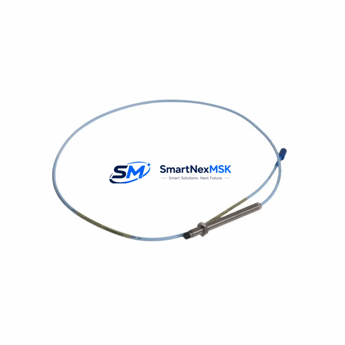
The 330103-06-16-10-02-00 is a 5-metre cable extension transducer with an 8 mm probe tip, designed to interface directly with Bently Nevada 3300 XL monitor cards including the 3300/16 and 3300/20 series. It operates on the standard -24 VDC proximitor supply and outputs a linear voltage signal proportional to the gap between the probe tip and the observed shaft or target surface. The transducer is fully compatible with the 330180 proximitor/driver and the 330130 extension cable system, making it a straightforward replacement for worn, damaged, or end-of-life units in the field.
Upgrade Compatibility Table
| Parameter | Detail |
|---|---|
| SKU / Part Number | 330103-06-16-10-02-00 |
| Series | Bently Nevada 3300 XL |
| Probe Tip Diameter | 8 mm |
| Cable Length | 5 metres (extension) |
| Supply Voltage | -24 VDC (standard 3300 XL proximitor supply) |
| Output Signal | Linear DC voltage, -18 VDC nominal gap |
| Compatible Proximitor | Bently Nevada 330180 |
| Compatible Extension Cable | Bently Nevada 330130 |
| Compatible Monitor Cards | 3300/16, 3300/20, 3300 XL series |
| Installation | Direct drop-in; no rack modification required |
| Communication / Protocol | Analog voltage output; compatible with 3500 Series migration path |
| Replacement Recommendation | Direct replacement for 330103-06-16-10-02-00; verify gap voltage at commissioning |
| Commissioning Note | Re-establish gap voltage per OEM specification; verify OK/NOT OK relay logic |
| Warranty | 12 Months |
Retrofit Planning for Existing Automation Systems
Retrofitting a 3300 XL proximity transducer system requires a structured approach that accounts for the full signal chain from the probe tip through to the monitor card and ultimately the control system or DCS. When replacing the 330103-06-16-10-02-00, engineers should begin by confirming the existing 330180 proximitor condition — a degraded proximitor will produce erratic gap voltage even with a new probe installed. If the proximitor is also being replaced, verify that the new unit is calibrated to the same sensitivity curve (200 mV/mil or 7.87 V/mm) to avoid false alarm conditions on the 3300/16 or 3300/20 monitor card.
The extension cable assembly, typically a 330130 series cable, should be inspected for jacket integrity and connector condition before reuse. In high-vibration environments or where cable routing passes through conduit with sharp bends, replacing the extension cable alongside the transducer is strongly recommended to prevent intermittent signal faults after commissioning. Connector torque specifications must be followed precisely — over-tightening the coaxial connector at the proximitor junction is a common cause of signal degradation in the field.
For sites migrating from the legacy 3300 Series to the Bently Nevada 3500 Series machinery protection platform, the 330103-06-16-10-02-00 transducer remains compatible as an interim measure while the 3500/42M or 3500/45 monitor modules are being commissioned. The 3500 Series rack accepts the same analog transducer signal, allowing the existing probe and extension cable to remain in service during the transition. This approach significantly reduces downtime by decoupling the transducer replacement from the monitor card upgrade schedule.
When planning a control cabinet upgrade that includes replacing the 3300 XL rack with a 3500/20 rack interface module, engineers should also account for the I/O terminal block wiring changes. The 3500 Series uses a different terminal assignment for the OK relay and buffered output connections compared to the 3300 XL, so DCS input cards and interlock logic must be reviewed before cutover. If the site uses a Rockwell Automation ControlLogix or CompactLogix PLC to process the vibration OK signal, the ladder logic rung associated with the machinery protection interlock should be verified and tested in simulation before the live cutover.
For systems where the vibration signal feeds into a GE Fanuc Series 90-30 or Siemens S7-300 analog input module, the signal scaling configuration in the PLC program must be confirmed against the new transducer’s sensitivity specification. A mismatch between the configured mV/mil sensitivity and the actual transducer output will result in incorrect engineering unit display on the HMI — whether that is a Wonderware InTouch panel, a Siemens TP700 Comfort HMI, or a Rockwell FactoryTalk View SE station. HMI tag scaling should be reviewed and updated as part of the commissioning checklist.
Sites operating with a Modbus RTU or PROFIBUS DP communication link between the machinery protection system and the plant DCS should verify that the monitor card’s communication module — such as the Bently Nevada 3500/92 communication gateway — is correctly configured to map the new channel data to the existing DCS tag addresses. A channel address mismatch after replacement will cause the DCS historian to log incorrect vibration data, which can affect predictive maintenance trending and compliance reporting.
Downtime Control During System Migration
Minimizing downtime during a proximity transducer replacement on a critical rotating machine requires pre-staging all replacement components, completing all documentation reviews offline, and establishing a clear go/no-go decision point before the machine is taken out of service. For the 330103-06-16-10-02-00 replacement, the recommended approach is to pre-configure the replacement transducer and proximitor assembly on the bench, verify the gap voltage output at the nominal 1.0 mm gap using a calibrated gap simulator, and confirm the OK relay output before the unit is installed in the field.
Where the machine cannot be taken offline for an extended period, a hot-swap approach using a pre-wired spare transducer assembly can reduce the physical installation time to under 30 minutes. The original program logic in the PLC or safety system should not be modified during the transducer swap — only the physical transducer, extension cable, and proximitor are replaced. All interlock bypasses applied during the maintenance window must be documented and removed immediately after commissioning is confirmed.
After installation, the gap voltage should be measured at the proximitor output terminal and compared against the OEM-specified nominal value. The monitor card’s OK/NOT OK status should be verified on the 3300/16 or 3300/20 front panel before the bypass is removed. A final check of the DCS display and historian tag confirms that the signal chain is intact and the machine is ready to return to service. All commissioning steps, measured values, and sign-off records should be retained as part of the site’s maintenance management system documentation.
Retrofit Support FAQ
Q: Is the 330103-06-16-10-02-00 a direct drop-in replacement for the original Bently Nevada part?
A: Yes. The 330103-06-16-10-02-00 is a direct replacement for the original OEM part of the same SKU. No rack modification, re-wiring, or software change is required for a like-for-like swap. Gap voltage should be verified at commissioning per standard procedure.
Q: What commissioning steps are required after installation?
A: After physical installation, measure the gap voltage at the proximitor output terminal and confirm it falls within the OEM-specified range for the target gap distance. Verify the OK relay status on the monitor card front panel, confirm the DCS or PLC is receiving the correct signal, and remove all maintenance bypasses before returning the machine to service.
Q: How do I verify wiring compatibility when replacing the transducer in an existing 3300 XL rack?
A: The 330103-06-16-10-02-00 uses the standard 3300 XL coaxial connector and terminal block wiring. Confirm that the extension cable connector is fully seated and torqued to specification at both the probe and proximitor ends. Check the terminal block for corrosion or loose connections before applying power.
Q: What warranty coverage is provided, and has the unit been tested before shipment?
A: All units carry a 12-month warranty covering manufacturing defects and functional performance. Each unit undergoes output signal verification and functional testing prior to shipment. Test records are available upon request for quality-critical applications.
© 2026 SMARTNEXMSK. All rights reserved.
Original Source: https://smartnexmsk.com
Contact: sales@smartnexmsk.com | +86 18259474341


