Bently Nevada 330103-09-16-10-02-00 Maintenance-Ready Spare for 3300 XL Automation
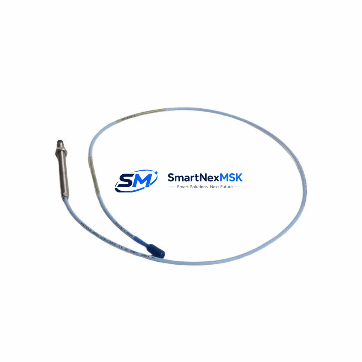
The Bently Nevada 330103-09-16-10-02-00 is an original 8mm proximity transducer engineered for the 3300 XL Series continuous vibration monitoring system. In rotating machinery protection environments — turbines, compressors, pumps, and gearboxes — this transducer serves as the primary sensing element for radial shaft vibration, axial position, and differential expansion measurement. When this component fails or degrades, the entire machinery protection loop is compromised, creating immediate unplanned downtime risk. Stocking a verified replacement is the single most effective action a maintenance team can take to protect uptime.
For maintenance engineers managing aging 3300 XL installations, the 330103-09-16-10-02-00 represents a direct, pin-compatible replacement that requires no reconfiguration of the monitor rack. The 8mm tip diameter, 5-metre extension cable configuration, and -18.0 Vdc nominal bias voltage are factory-set and verified prior to shipment. Each unit undergoes output linearity and sensitivity testing before dispatch, ensuring the replacement transducer meets the original Bently Nevada specification of 7.87 V/mm (200 mV/mil) sensitivity.
Spare Maintenance Table
| Parameter | Specification |
|---|---|
| Part Number | 330103-09-16-10-02-00 |
| Series | Bently Nevada 3300 XL |
| Transducer Tip Diameter | 8 mm |
| Sensitivity | 7.87 V/mm (200 mV/mil) |
| Nominal Bias Voltage | -18.0 Vdc |
| Linear Range | 0.25 mm – 2.25 mm (10 – 90 mil) |
| Cable Length (Extension) | 5 m (16 ft) |
| Operating Temperature | -35°C to +121°C |
| Compatibility | 3300 XL Monitor Rack, 3300/16 Monitor, 3500/42 Monitor |
| Installation | M10 x 1 thread, locknut included |
| Application Environment | Turbines, Compressors, Pumps, Gearboxes |
| Maintenance Recommendation | Replace every 5 years or upon bias voltage drift >10% |
| Warranty | 12 Months from shipment date |
| Origin | USA (Original Bently Nevada) |
Maintenance Planning for Continuous Operation
A proximity transducer replacement should never be treated as an isolated swap. When a 330103-09-16-10-02-00 is removed from service, the maintenance window presents an opportunity to inspect and verify the condition of every component in the same vibration monitoring loop. The 330130-080-01-00 extension cable connecting the transducer to the proximitor should be inspected for jacket damage, connector corrosion, and continuity — a degraded cable will introduce noise into the vibration signal even with a new transducer installed.
The 330180-91-00 proximitor/driver (or its 3300 XL equivalent) should be bench-tested for output voltage and gap voltage linearity before the system is returned to service. If the proximitor shows drift, replacing the transducer alone will not restore measurement accuracy. In the same cabinet inspection, verify the condition of the 3300/16 dual-channel vibration monitor card — check for alarm relay contact wear, OK relay status, and any fault LED indications that may have been masked by the transducer fault.
Power supply integrity is critical in 3300 XL systems. The 3300/20 power supply module should be checked for output voltage stability under load; a sagging -24 Vdc rail will cause false OK dropouts across all transducer channels simultaneously. For sites running redundant monitoring, the 3300/25 relay output module and its associated terminal blocks should be inspected for loose connections that could cause spurious trips during the recommissioning sequence.
If the installation is part of a 3500 Series rack running in parallel for API 670 compliance, verify that the 3500/42M proximitor I/O module is correctly configured for the 8mm transducer gap range. Communication health between the rack and the System 1 Condition Monitoring software should be confirmed via the 3500/92 communication gateway before the machine is returned to full load. For sites using TDXnet or Modbus RTU integration to the DCS, verify that the transducer channel tag mapping remains intact after the replacement.
Procurement engineers should note that the 330103-09-16-10-02-00 is frequently paired with the 330105-02-12-10-02-00 (5mm transducer) in mixed-measurement racks. Maintaining a minimum of two units of each transducer type in the site spare parts inventory is recommended for facilities with more than four monitored machines. Long lead times on original Bently Nevada components make pre-positioned stock essential for rapid downtime recovery.
Site Replacement Workflow
Step 1 — Pre-Replacement Verification: Confirm the replacement 330103-09-16-10-02-00 bias voltage reads between -17.0 and -19.0 Vdc at the nominal 1.0 mm gap using a calibrated gap tool. Document the reading before installation.
Step 2 — Safe Isolation: Place the affected monitor channel in bypass mode via the 3300/16 or 3500/42 front panel to prevent spurious machine trips during the swap. Notify the control room before proceeding.
Step 3 — Mechanical Removal: Loosen the locknut and back out the transducer using the correct spanner. Note the gap setting (number of turns from contact) to use as a reference for the replacement installation.
Step 4 — Installation and Gapping: Thread the new 330103-09-16-10-02-00 to the recorded gap position. Connect the extension cable and verify the bias voltage reads within specification on the monitor front panel or via System 1.
Step 5 — Functional Test: Remove bypass mode and confirm the channel returns to OK status. Verify vibration readings are within expected baseline range before returning the machine to service. Log the replacement in the site CMMS with the new unit serial number and installation date.
This workflow minimises downtime to under 45 minutes for a trained technician and eliminates the risk of incorrect gapping that can cause immediate re-failure or false alarm conditions.
Spare Parts Support FAQ
Q: Is the 330103-09-16-10-02-00 compatible with both 3300 XL and 3500 Series monitor racks?
A: Yes. The 8mm transducer is electrically compatible with both the 3300 XL and 3500/42 monitor modules when the proximitor driver is correctly matched. Always verify the proximitor model number before ordering to ensure the complete loop is compatible.
Q: How is each unit tested before shipment?
A: Every 330103-09-16-10-02-00 unit is tested for output linearity, sensitivity (7.87 V/mm ±5%), and bias voltage at the nominal gap before dispatch. A test report is available upon request. Units are shipped in anti-static packaging with protective tip covers.
Q: What is the recommended spare parts inventory strategy for this transducer?
A: For facilities with 4 or more monitored machines, we recommend maintaining a minimum of 2 units on-site. For critical machinery (main steam turbines, centrifugal compressors), a minimum of 4 units is advisable given the potential cost of unplanned downtime versus the relatively low cost of the spare.
Q: What does the 12-month warranty cover?
A: The 12-month warranty covers manufacturing defects, sensitivity drift beyond ±10% of specification, and connector or cable integrity failures under normal operating conditions. Warranty claims are supported with a replacement unit dispatched within 5 business days of fault confirmation.
© 2026 SMARTNEXMSK. All rights reserved.
Original Source: https://smartnexmsk.com
Contact: sales@smartnexmsk.com | +86 18259474341


