Bently Nevada 330103-09-19-05-02-00 Maintenance-Ready Spare for 3300 XL Automation
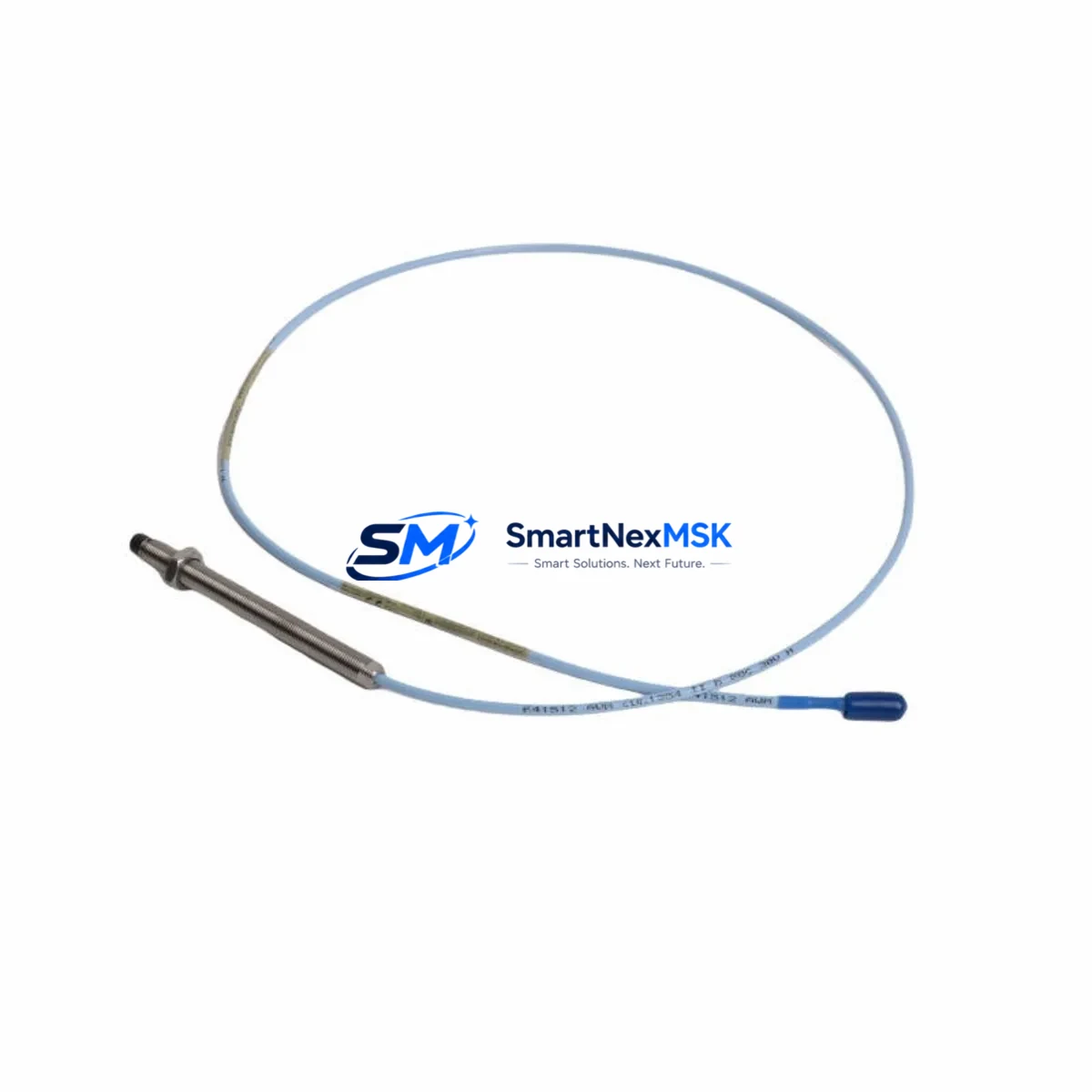
The Bently Nevada 330103-09-19-05-02-00 is an original 8mm proximity transducer with a 5-metre extension cable, engineered for the 3300 XL continuous vibration monitoring system. In rotating machinery protection environments — turbines, compressors, pumps, and gearboxes — this transducer is a front-line component whose failure directly triggers unplanned downtime. Holding a verified spare on the shelf is not optional; it is a maintenance discipline that separates reactive plants from reliability-driven operations.
Every unit shipped by SMARTNEXMSK is sourced from authorised supply channels, subjected to pre-shipment electrical verification, and covered by a 12-month warranty. Fast global dispatch ensures that when a transducer fails during a night shift or a weekend turnaround, a replacement is already in transit before the morning meeting.
Spare Maintenance Table
| Parameter | Specification |
|---|---|
| Part Number | 330103-09-19-05-02-00 |
| Brand | Bently Nevada |
| Series | 3300 XL |
| Sensor Type | Eddy-Current Proximity Transducer |
| Probe Tip Diameter | 8 mm |
| Extension Cable Length | 5 m (16.4 ft) |
| Nominal Gap Voltage | −10 VDC (at 1.27 mm / 50 mil gap) |
| Supply Voltage | −24 VDC (via 3300 XL driver/monitor) |
| Output Range | −2 VDC to −18 VDC |
| Scale Factor | 7.87 V/mm (200 mV/mil) |
| Frequency Response | DC to 10 kHz (−3 dB) |
| Operating Temperature | −35 °C to +177 °C (probe); −20 °C to +85 °C (extension) |
| Target Material Compatibility | AISI 4140 steel (standard); other alloys require calibration verification |
| Connector | MIL-C-5015 (probe end); BNC or equivalent (driver end) |
| Ingress Protection | IP67 (probe assembly) |
| Compatible Monitor | Bently Nevada 3300 XL series (3300/16, 3300/20, 3300/25, 3300/55) |
| Compatible Driver | 330180 series proximitor / extension driver |
| Installation Thread | M10 × 1 (standard) |
| Origin | United States |
| Warranty | 12 Months (SMARTNEXMSK) |
| Pre-shipment Test | Electrical continuity, gap voltage, scale factor verification |
Maintenance Planning for Continuous Operation
When a 330103-09-19-05-02-00 proximity transducer is flagged during a routine vibration survey or trips a 3300 XL monitor channel, the replacement task rarely ends with the probe alone. A disciplined maintenance engineer will use the opportunity to inspect the entire measurement chain and the surrounding cabinet infrastructure.
Begin with the 330180-series proximitor / extension driver that conditions the transducer signal. A degraded driver can mimic a faulty probe, and replacing the transducer without verifying driver output voltage will leave the root cause unresolved. Check the driver’s power supply rail — the 3300 XL power supply module (typically a 3300/05 or equivalent) should deliver a stable −24 VDC; any ripple or sag will corrupt gap readings across all channels simultaneously.
Inspect the extension cable assembly for jacket abrasion, connector corrosion, and shield continuity. In high-vibration environments, cable fatigue at the probe-to-extension junction is a common failure mode that is easily overlooked when attention is focused on the probe tip. While the cabinet door is open, verify the 3300 XL monitor module itself — check for alarm setpoint drift, relay output integrity, and communication card status if the monitor feeds a DCS or safety system via a 3300/20 or 3300/55 communication module.
For plants running parallel redundancy, confirm that the redundant proximitor channel is active and reading within tolerance. A single-channel failure in a 1oo2 voting architecture does not trip the machine, but it eliminates the protection margin until the spare is installed. Document the as-found gap voltage before removal — this value, compared against the original commissioning record, reveals shaft centreline migration and bearing wear trends that inform the next planned outage scope.
At the terminal strip level, inspect DIN-rail mounted signal isolators and surge protection modules on the transducer wiring. These components absorb electrical transients from nearby VFDs, welding equipment, or lightning events, and their degradation is invisible until a transducer or monitor card is damaged. Fuse holders and miniature circuit breakers protecting the −24 VDC supply rail should also be tested for contact resistance. Finally, if the machine is part of an API 670-compliant protection system, verify that the overspeed detection module and any thrust position monitor channels sharing the same rack are unaffected before returning the machine to service.
Site Replacement Workflow
Step 1 — Permit and isolation. Obtain a hot-work or confined-space permit as applicable. Isolate the monitor channel in bypass mode per your site MOC procedure to prevent a spurious trip during probe removal. Do not de-energise the entire 3300 XL rack unless required — other channels must remain in service to protect the machine during the swap.
Step 2 — As-found documentation. Record the gap voltage displayed on the monitor or via the proximitor test point before disconnecting the extension cable. Photograph the probe installation depth and locknut position. This data is essential for setting the replacement probe to the correct gap without a full recommissioning sweep.
Step 3 — Removal. Disconnect the extension cable at the proximitor. Unscrew the probe from the bracket, noting the number of turns to reach the as-found gap. Inspect the bracket threads and the shaft target area for damage or contamination.
Step 4 — Installation of 330103-09-19-05-02-00. Thread the new probe to the same depth as the removed unit. Connect the extension cable and verify the gap voltage at the proximitor test point. Adjust probe depth in 0.25 mm increments until the gap voltage matches the nominal −10 VDC ± 0.5 V. Tighten the locknut to the specified torque and apply thread-locking compound if required by site standards.
Step 5 — Functional verification. Remove the channel bypass. Observe the monitor for stable readings with no alarms. Perform a static calibration check if the site procedure requires it. Update the maintenance management system with the replacement date, as-found gap voltage, and as-left gap voltage.
Step 6 — Spare replenishment. Raise a purchase order for a replacement spare immediately after installation. A zero-spare position on a critical transducer is an unacceptable risk. SMARTNEXMSK maintains stock of 330103-09-19-05-02-00 and compatible 3300 XL components for same-week dispatch.
Spare Parts Support FAQ
Q1: Is the 330103-09-19-05-02-00 a direct drop-in replacement for older 330103 variants?
The 330103-09-19-05-02-00 is part of the Bently Nevada 330103 family and is electrically compatible with 3300 XL monitor racks. However, the suffix digits encode cable length, connector type, and temperature rating. Confirm that the replacement suffix matches your installed configuration — particularly the extension cable length (19 = 5 m in this variant) and the armour/jacket specification — before installation. If you are replacing an earlier 330103 variant with a different suffix, contact SMARTNEXMSK for a compatibility cross-reference.
Q2: What pre-shipment testing does SMARTNEXMSK perform on this transducer?
Each unit undergoes electrical continuity verification, gap voltage measurement at the nominal 1.27 mm gap, and scale factor confirmation against the 7.87 V/mm specification. Units that fall outside tolerance are quarantined and not shipped. A test report is available on request for critical applications.
Q3: How should this spare be stored to maintain its service life?
Store the transducer in its original packaging in a dry, temperature-controlled environment (0 °C to 40 °C, <85% RH non-condensing). Keep the probe tip protected with the supplied cap and avoid coiling the extension cable tighter than a 50 mm bend radius. Inspect stored spares annually for connector corrosion and cable jacket integrity. Shelf life under proper storage conditions exceeds five years.
Q4: What is covered under the 12-month warranty?
SMARTNEXMSK’s 12-month warranty covers manufacturing defects, electrical failure under normal operating conditions, and connector integrity. It does not cover damage resulting from incorrect installation gap, mechanical impact, chemical exposure beyond the rated environment, or operation outside the specified supply voltage range. Warranty claims are processed with return of the defective unit and a completed failure report. Replacement units are dispatched within 5 business days of claim approval.
© 2026 SMARTNEXMSK. All rights reserved.
Original Source: https://smartnexmsk.com
Contact: sales@smartnexmsk.com | +86 18259474341


